
User's Manual


DynoWare EX+ Upgrade For The Model 248 Dynamometer
APPENDIXA
Installation
A-6
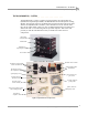
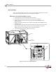
WIRING THE BREAKOUT BOARD
When attaching cables, refer to Figure A-6 for cable location and Figure A-7 for
Breakout board wiring information.
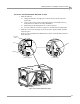
1 Attach the data acquisition cable coming from the optical pickup card on the dyno
to the Breakout board. The data acquisition cable has four wires which connect to
the wiring block labeled DRUM 1.
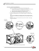
2 Attach the wires from the air pressure switch, located on the prop air regulator
assembly, to the wiring block labeled PRESS on the Breakout board. Each wire
may attach in either position.
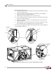
3 Attach the cable coming from the EPR to the Breakout board. The EPR cable has
five wires which connect to the wiring block labeled LOAD CONTROL.
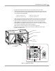
4 Attach the brake wires from the brake solenoid, located on the prop air regulator
assembly, to the wiring block labeled BRAKE on the Breakout board. Each wire
may attach in either position.
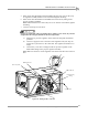
5 Attach the temperature sensor cable to the Breakout board. The temperature
sensor cable has five wires which connect to the wiring block labeled TEMP on
the Breakout board.
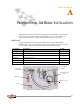
• Red wire connects to R1 • White wire connects to W1
• Black wire connects to B1 • Silver wire connects to S1
• Black wire connects to V- • Red wire connects to V+
• White wire connects to O+ • Green wire connects to O-
• Silver or ground (shield) wire connects to SH
• Green wire connects to G1 • White wire connects to W1
• Black wire connects to B1 • Red wire connects to R1
• Silver or ground (shield) wire connects to S1