
User's Manual

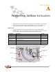


PROPORTIONAL AIR BRAKE INSTALLATION
Installation
Version 2 DynoWare EX+ Upgrade For The Model 248 Dynamometer
A-7
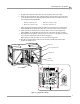
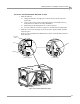
Figure A-6: Routing Cables—Breakout Board
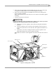
6 The Breakout board jumper settings are preset, however, verify jumpers J1 and J2
are set for the proportional air brake as shown in Figure A-7.
7 Plug the 25 pin DynoWare cable into the bottom of the Breakout board and
tighten the thumb screws.
8 Continue with “Wiring the DynoWare EX+ Modules” on page 8.
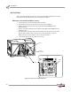
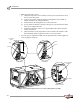
Figure A-7: Prop Air—Wiring
EPR cable
data acquisition
cable
brake solenoid
wires
air pressure
switch wire
DynoWare cable
temperature
sensor cable
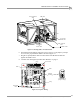
drum 1
press
load control
brake
temp
DynoWare
cable
jumpers
J1 and J2
proportional air
jumper settings