
User's Manual
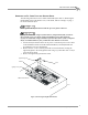
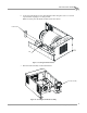
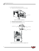

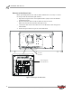
Table Of Contents
- Cover
- Copyright
- Table of Contents
- Air Brake and EEC Kit Installation
- Introduction
- Air Brake
- Removing the Drum Module Hood, Side Drum Cover, Center Panel, and Tire Carriage
- Removing the Pit Cover Plate and Upright Brace
- Installing the Air Brake Assembly
- Routing the Air Brake Cable
- Connecting the Shop Air-200i/250i
- Connecting the Shop Air-200iP/250iP
- Adjusting the Brake Pad Clearance
- Final Adjustments and Tests-200i/250i
- Final Adjustments and Tests-200iP/250iP
- EEC Finger Guards-200i/250i
- EEC Finger Guards-200iP/250iP
- Door Safety Switch
- Replacing the Drum Module Hood, Side Drum Cover, Center Panel, and Tire Carriage-200i/250i
- Replacing Pit Cover Plates and Upright Brace-200iP/250iP
INSTALLATION GUIDE
Air Brake
Version 1 Air Brake and EEC Kit Installation Guide for 200i/250i and 200iP/250iP Motorcycle Dynamometers
7
REMOVING THE PIT COVER PLATE AND UPRIGHT BRACE
The following instructions are for model 200iP/250iP dynos. Refer to “Removing the
Drum Module Hood, Side Drum Cover, Center Panel, and Tire Carriage” on page 3
for model 200i/250i dynos.
Never operate the dynamometer with the pit cover plates removed.
Dynojet recommends using a T30 Torx driver (Snap-On PFTx30E) to remove
the 1/4-inch screws. For dynos with serial numbers lower than 2030152,
Dynojet recommends using a hardened 5/32-inch hex driver (such as Snap-On
FA5E). A standard allen key may round off in the shallow screw head.
1 Turn off the dyno and disconnect the AC power cord from its power source. Refer
to the Installation Guide for Model 200iP/250iP Motorcycle Pit Dynamometers
(P/N 98229103) for more information.
2 Remove the two 1/4-20 x 5/8-inch pan head screws and locknuts securing the
right drum guard to the drum guard mount using a 5/32-inch allen tool or a #30
torx tool and set aside.
3 Remove the right drum guard and set aside.
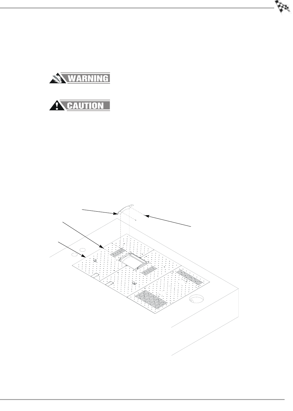
Figure 5: Removing the Right Drum Guard
FRONTOFDYNO
PD072
screw
right drum guard
right pit cover plate
locknut