
User's Manual
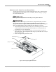
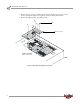
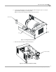
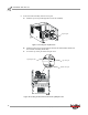

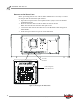
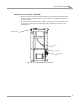
Table Of Contents
- Cover
- Copyright
- Table of Contents
- Air Brake and EEC Kit Installation
- Introduction
- Air Brake
- Removing the Drum Module Hood, Side Drum Cover, Center Panel, and Tire Carriage
- Removing the Pit Cover Plate and Upright Brace
- Installing the Air Brake Assembly
- Routing the Air Brake Cable
- Connecting the Shop Air-200i/250i
- Connecting the Shop Air-200iP/250iP
- Adjusting the Brake Pad Clearance
- Final Adjustments and Tests-200i/250i
- Final Adjustments and Tests-200iP/250iP
- EEC Finger Guards-200i/250i
- EEC Finger Guards-200iP/250iP
- Door Safety Switch
- Replacing the Drum Module Hood, Side Drum Cover, Center Panel, and Tire Carriage-200i/250i
- Replacing Pit Cover Plates and Upright Brace-200iP/250iP
Air Brake and EEC Kit Installation Guide for 200i/250i and 200iP/250iP Motorcycle Dynamometers
AIR BRAKE AND EEC KIT
Air Brake
10
INSTALLING THE AIR BRAKE ASSEMBLY
The following instructions are for both the model 200i/250i above ground and
200iP/250iP pit motorcycle dynamometers. If you are not installing the air brake skip
this section and refer to “EEC Finger Guards—200i/250i” on page 20, “EEC Finger
Guards—200iP/250iP” on page 23, and “Door Safety Switch” on page 29.
1 Turn off the dyno and disconnect the AC power cord from its power source.
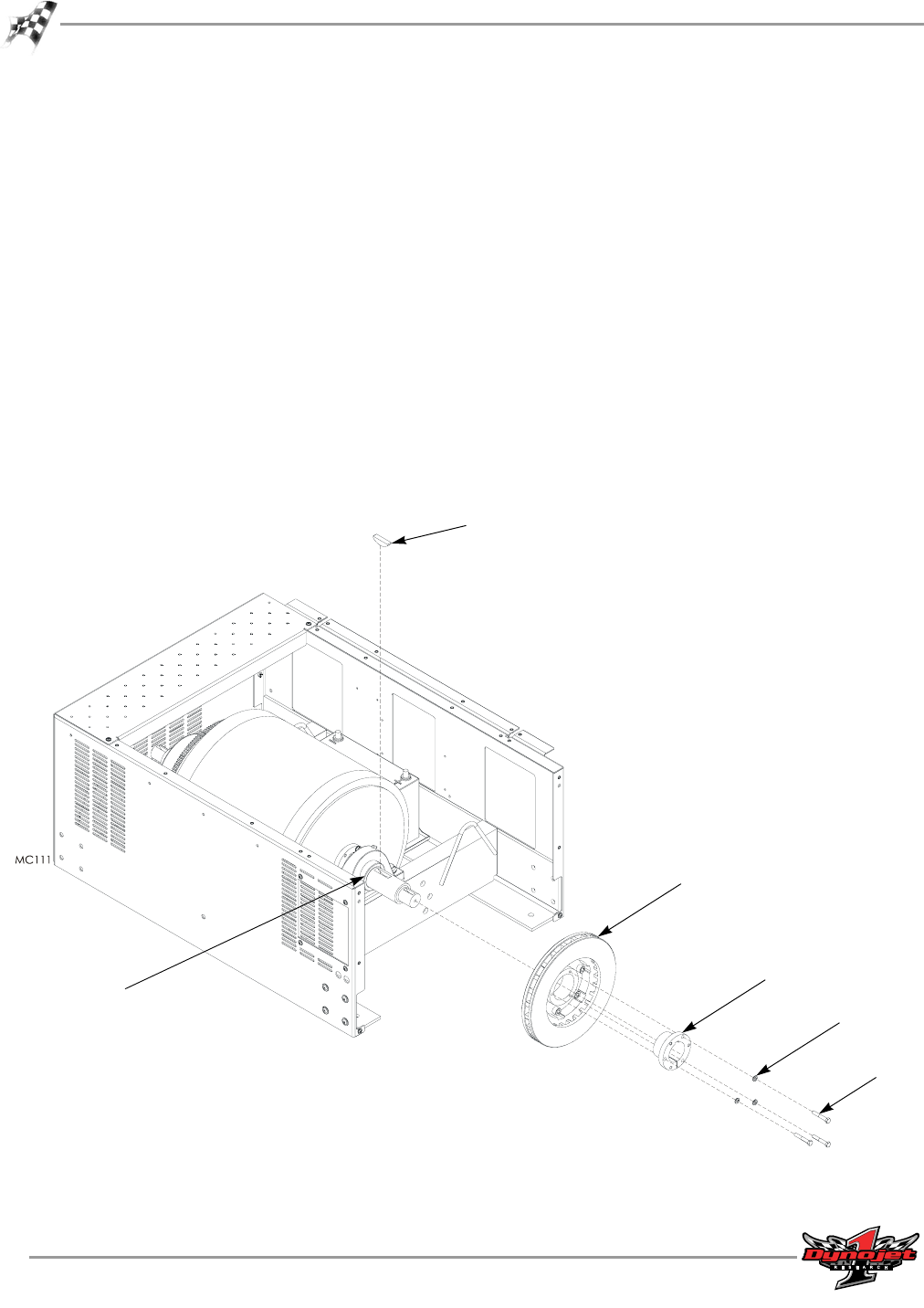
2 Insert the woodruff key into the dyno shaft.
3 Slide the brake rotor with taper lock onto the shaft and align it, so that the taper
lock touches the bearing lock collar on the dyno shaft.
4 Set up a dial indicator on the disc braking surface to measure the run-out. The
maximum allowable run-out is +/- 0.005 inches.
5 Tighten the three bolts in a clockwise rotation to help minimize the run out,
torquing to 15 foot-pounds.
Note: If necessary, readjust the taper lock and brake rotor to ensure the run-out is
less than +/- 0.005 inches.
Note: For clarity, only the drum module is shown.
Figure 8: Securing the Brake Rotor
bearing lock
collar
bolt
washer
taper lock
brake rotor
woodruff key