
User's Manual
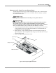
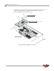
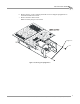
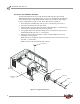
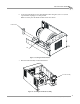
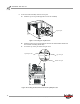

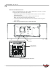
Table Of Contents
- Cover
- Copyright
- Table of Contents
- Air Brake and EEC Kit Installation
- Introduction
- Air Brake
- Removing the Drum Module Hood, Side Drum Cover, Center Panel, and Tire Carriage
- Removing the Pit Cover Plate and Upright Brace
- Installing the Air Brake Assembly
- Routing the Air Brake Cable
- Connecting the Shop Air-200i/250i
- Connecting the Shop Air-200iP/250iP
- Adjusting the Brake Pad Clearance
- Final Adjustments and Tests-200i/250i
- Final Adjustments and Tests-200iP/250iP
- EEC Finger Guards-200i/250i
- EEC Finger Guards-200iP/250iP
- Door Safety Switch
- Replacing the Drum Module Hood, Side Drum Cover, Center Panel, and Tire Carriage-200i/250i
- Replacing Pit Cover Plates and Upright Brace-200iP/250iP
INSTALLATION GUIDE
Air Brake
Version 1 Air Brake and EEC Kit Installation Guide for 200i/250i and 200iP/250iP Motorcycle Dynamometers
15
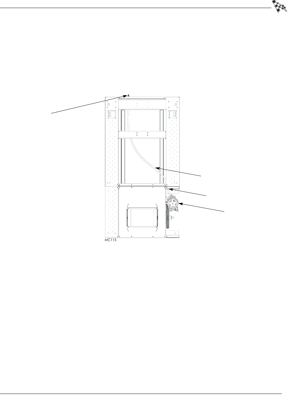
CONNECTING THE SHOP AIR—200I/250I
1 Route the air hose from the air brake through the access hole in the drum module
upright, under the carriage frame brace, and connect to the bulkhead fitting at the
front of the dyno.
2 You will need to provide an air hose nipple (1/4-inch NPT) to connect your clean,
dry shop air supply (60 psi, 415 kilopascal, max constant line pressure) to the
dynamometer.
Figure 16: Connecting the Air Hose—200i/250i
air pump
air hose
bulkhead fitting
access hole