
User's Manual

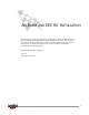
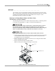
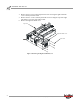
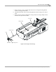
Table Of Contents
- Cover
- Copyright
- Table of Contents
- Air Brake and EEC Kit Installation
- Introduction
- Air Brake
- Removing the Drum Module Hood, Side Drum Cover, Center Panel, and Tire Carriage
- Removing the Pit Cover Plate and Upright Brace
- Installing the Air Brake Assembly
- Routing the Air Brake Cable
- Connecting the Shop Air-200i/250i
- Connecting the Shop Air-200iP/250iP
- Adjusting the Brake Pad Clearance
- Final Adjustments and Tests-200i/250i
- Final Adjustments and Tests-200iP/250iP
- EEC Finger Guards-200i/250i
- EEC Finger Guards-200iP/250iP
- Door Safety Switch
- Replacing the Drum Module Hood, Side Drum Cover, Center Panel, and Tire Carriage-200i/250i
- Replacing Pit Cover Plates and Upright Brace-200iP/250iP
INSTALLATION GUIDE
Air Brake
Version 1 Air Brake and EEC Kit Installation Guide for 200i/250i and 200iP/250iP Motorcycle Dynamometers
3
. . . . . . . . . . . . . . . . . . . . . . . . . . . . . . . . . . .
AIR BRAKE
The air brake is an electro-pneumatic braking system which quickly slows the drum
after a run and locks it from turning. The air brake includes the brake rotor, air brake
assembly, and the brake bracket and is easily installed onto the dyno. Use the
following instructions to install your air brake.
REMOVING THE DRUM MODULE HOOD, SIDE DRUM COVER,
CENTER PANEL, AND TIRE CARRIAGE
The following instructions are for model 200i/250i dynos. Refer to “Removing the Pit
Cover Plate and Upright Brace” on page 7 for model 200iP/250iP dynos.
Dynojet recommends using a T30 Torx driver (Snap-On PFTx30E) to remove
the 1/4-inch screws. For dynos with serial numbers lower than 2030152,
Dynojet recommends using a hardened 5/32-inch hex driver (such as Snap-On
FA5E). A standard allen key may round off in the shallow screw head.
Never operate the dynamometer with the drum module hood removed.
1 Turn off the dyno and disconnect the AC power cord from its power source. Refer
to the Installation Guide for Model 200i and 250i Motorcycle Dynamometers
(P/N 98220104) for more information.
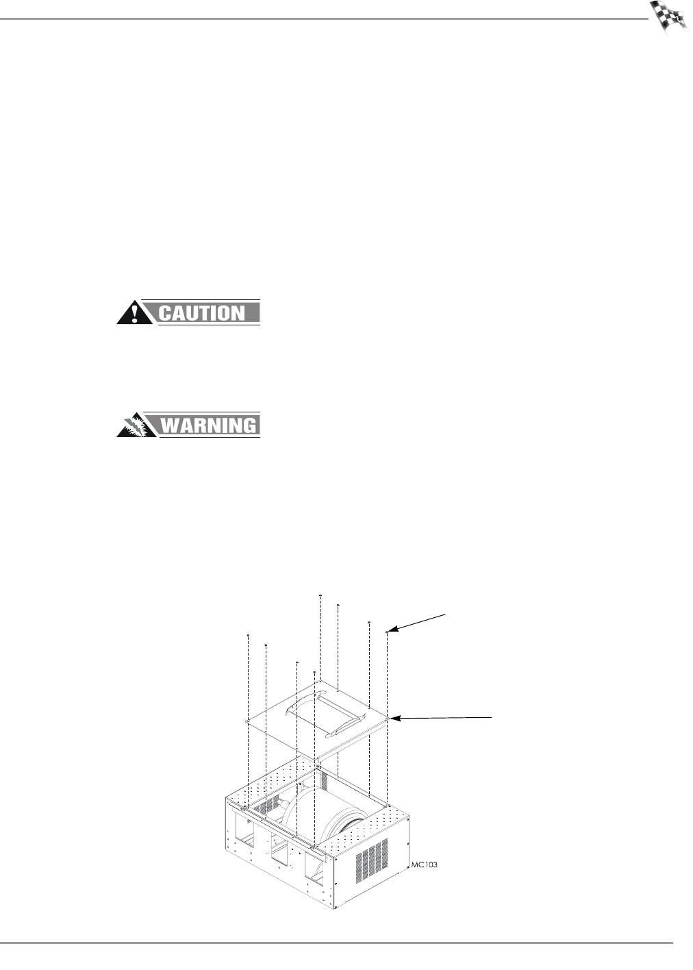
2 Remove the eight 1/4-20 x 5/8-inch pan head screws securing the drum module
hood to the dyno and set aside.
3 Remove the drum module hood and set aside.
Note: For clarity, the retarder and carriage are not shown.
Figure 1: Removing the Drum Module Hood
drum module hood
screw