
Automobile Electronics User Manual

3 - 14 Document #98219100
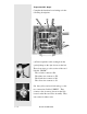
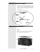
Proportional Air Step 6
Complete the breakout board wiring as in the
following descriptions:
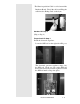
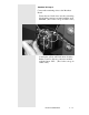
(A) Data acquisition cable coming from the
optical pickup on the dyno shown on the left.
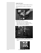
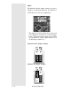
These four wires go to the section of the card
Labeled “DRUM”:
The red wire connects to R1.
The white wire connects to W1.
The black wire connects to B1.
The silver wire connects to S1.
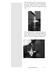
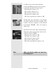
(B) One yellow and one black wire go to the
two connections Labeled “PRESS”. They
connect to the air sensor (shown on the left)
located on the Booster Valve Assembly. They
can connect in either order.
C
B
A
D
E
C
B
A
D
E