©2004-2005 Dynojet Research, Inc. All Rights Reserved. Eddy Current Brake Installation and User Guide For Model 224 Pit Automotive Dynamometers. This manual is copyrighted by Dynojet Research, Inc., hereafter referred to as Dynojet, and all rights are reserved. This manual, and the software described in it, is furnished under license and may only be used or copied in accordance with the terms of such license.
TABLE OF CONTENTS Chapter 1 Eddy Current Brake Installation Introduction . . . . . . . . . . . . . . . . . . . . . . . . . . . . . . . . . . . . . . . . . . . . . . . . . . 1-2 Conventions Used In This Manual . . . . . . . . . . . . . . . . . . . . . . . . . . . . . . . 1-3 Technical Support . . . . . . . . . . . . . . . . . . . . . . . . . . . . . . . . . . . . . . . . . . . 1-3 Parts List . . . . . . . . . . . . . . . . . . . . . . . . . . . . . . . . . . . . . . . . . . . . . . . . . .
TA B L E O F C O N T E N T S Chapter 3 Basic Dynamometer Operation Loading the Car . . . . . . . . . . . . . . . . . . . . . . . . . . . . . . . . . . . . . . . . . . . . . . . 3-2 Connecting The RPM Pickup . . . . . . . . . . . . . . . . . . . . . . . . . . . . . . . . . . . . 3-5 RPM Pickup Descriptions . . . . . . . . . . . . . . . . . . . . . . . . . . . . . . . . . . . . . . 3-5 Connecting the Secondary Inductive Pickup . . . . . . . . . . . . . . . . . . . . . . .
CHAPTER 1 EDDY CURRENT BRAKE INSTALLATION This document provides instructions for installing the eddy current brake (retarder) to the Dynojet model 224 pit automotive dynamometer (dyno). This document also provides instructions for installing and calibrating the load cell and basic dynamometer operation. To ensure safety and accuracy in the procedures, perform the procedures as they are described.
CHAPTER 1 Introduction INTRODUCTION ................................... Before installing your eddy current brake, please take a moment to read this guide for installation instructions and other important information. This guide is designed to be a reference tool in your everyday work and includes the following chapters and information: EDDY CURRENT BRAKE INSTALLATION This chapter describes the procedures for installing the eddy current brake.
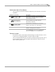
EDDY CURRENT BRAKE INSTALLATION Introduction CONVENTIONS USED IN THIS MANUAL The conventions used in this manual are designed to protect both the user and the equipment. Example of Convention RECORD # Description The Caution icon indicates a potential hazard to the dynamometer equipment. Follow all procedures exactly as they are described and use care when performing all procedures. The Warning icon indicates potential harm to the person performing a procedure and/or the dynamometer equipment.
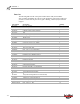
CHAPTER 1 Introduction PARTS LIST The following table lists all of the parts included in the Eddy Current Brake (P/N 72912002) Installation kit. Check your kit against the parts listed to make sure you have received all of the parts. If any part is missing, contact Dynojet Technical Support.
EDDY CURRENT BRAKE INSTALLATION Power Requirements and Installation POWER REQUIREMENTS AND INSTALLATION ................................... The following power requirements and instructions are for North America, Japan, and locations using 60 Hz power. All other locations should refer to the instructions found in Appendix B. The eddy current brake requires a dedicated 240VAC single phase power outlet rated for 30A for proper operation.
CHAPTER 1 Power Requirements and Installation TESTING FOR CORRECT VOLTAGES You must test the receptacle for proper voltages before the eddy current brake is connected to the outlet. If the voltage readings do not match the following table, DO NOT connect the brake. You must have a licensed electrician correct the power connection. Connecting the brake to the incorrect voltage can result in damage to the brake and will void the brake warranty. Contact Dynojet with any questions.
EDDY CURRENT BRAKE INSTALLATION Power Requirements and Installation REPLACING THE POWER PLUG Use the following instructions to replace the four wire plug and socket. The plug and socket configuration must be rated for at least 240VAC 30A and have a minimum of four conductors. The power cord that attaches to the brake has four conductors internally and their colors are brown, blue, black, and green/yellow. 1 2 3 4 Connect 240VAC single phase power between the brown and the blue wire connection points.
CHAPTER 1 Eddy Current Brake Installation EDDY CURRENT BRAKE INSTALLATION ................................... This section will walk you through removing the eddy current brake from the crate, installing the eddy current brake on model 224 pit automotive dynos, installing the Theta Controller, and routing cables. You will need to provide equipment capable of lifting the eddy current brake off the crate and into position in your dyno room. You will also need a pair of straps.
EDDY CURRENT BRAKE INSTALLATION Eddy Current Brake Installation UNPACKING THE EDDY CURRENT BRAKE 1 2 3 Remove the top and sides of the crate. Remove any hardware and parts boxes and set aside. Remove the uprights and cross members off the crate.
CHAPTER 1 Eddy Current Brake Installation 4 Remove the two screws securing each pit cover support. Set the screws and covers aside. RECORD # Be sure you record the dynamometer and/or eddy current brake number on the inside cover of this manual. pit cover support pit cover support EB096 brake number Figure 1-4: Remove the Pit Cover Supports INSTALLING THE BEARING The eddy current brake can be installed on either side of your dyno, the installation instructions are the same.
EDDY CURRENT BRAKE INSTALLATION Eddy Current Brake Installation INSTALLING THE SPLINE SHAFT AND DRIVELINE ASSEMBLY 1 Insert the spline shaft through the bearing and into the spline hub of drum. Note: Make sure the short spline end faces out. 2 3 4 Push the spline shaft as far as it will go. Torque the bearing mounting bolts to 57 ft.-lbs. Torque the two set screws on the bearing to 25 ft.-lbs.
CHAPTER 1 Eddy Current Brake Installation INSTALLING THE EDDY CURRENT BRAKE 1 2 Remove the four lag bolts securing the brake to the crate Place the keyed yoke onto the eddy current brake shaft.
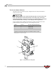
EDDY CURRENT BRAKE INSTALLATION Eddy Current Brake Installation 3 4 Place one nylon loop strap around the brake shaft with the yoke. Keep the strap close to the bearing. Place one nylon loop strap around the other side of the brake shaft. Keep the strap close to the bearing. Dynojet recommends using single loop style straps. 5 6 7 Place the nylon loop straps around the forklift forks. Slide the forklift forks together until the straps angle inward.
CHAPTER 1 Eddy Current Brake Installation 8 9 Line up the eddy current brake yoke with the driveline assembly. Slide the brake frame towards the dyno frame until they touch. Make sure the brake yoke is aligned with the driveline. 10 Secure the yoke to the driveline assembly using the four bolts removed earlier. Torque the bolts to 70 ft.-lbs. 11 Secure the brake frame to the dyno using eight 3/8 x 1-inch bolts and eight 5/16-inch hardened flat washers.
EDDY CURRENT BRAKE INSTALLATION Eddy Current Brake Installation INSTALLING THE PIT COVER SUPPORTS AND THETA CONTROLLER 1 Loosely secure the pit cover supports to the frame using two 1/4-20 x 3/4-inch button-head flange screws for each support. Note: Do not tighten the screws. 2 Verify the pit cover supports are flush with the top of the pit floor before you tighten the screws. 2a Place a straight edge across the pit cover supports.
CHAPTER 1 Eddy Current Brake Installation 3 4 Install the Theta Controller using four 8-32 x 3/8-inch screws. Install the cable routing channel using two screws.
EDDY CURRENT BRAKE INSTALLATION Eddy Current Brake Installation SECURING THE BRAKE TO THE DYNO PIT FLOOR 1 2 Install one foot on either side of the brake, as shown in Figure 1-13, using one 1/2-13 x 1.25-inch flange bolt and one 1/2-13-inch nylock nut (not visible). Install the Red Head Anchors. Refer to Appendix A for Red Head Anchor installation instructions.
CHAPTER 1 Eddy Current Brake Installation ROUTING THE BRAKE CABLES Refer to Figure 1-14 on page 1-18 for cable routing location information. 1 Route the temperature sensor cable from the eddy current brake over to the Breakout board. For more information on wiring the Breakout board refer to page 1-19. 2 3 4 5 6 Route the speed pick-up cable from the Breakout board over to the pick-up card.
EDDY CURRENT BRAKE INSTALLATION Eddy Current Brake Installation WIRING THE BREAKOUT BOARD Refer to Figure 1-15 on page 1-20 for Breakout board location information. 1 Attach the temperature sensor cable to the Breakout board. The temperature sensor cable has five wires which connect to the wiring block labeled TEMP. This cable was routed to the Breakout board on page 1-18.
CHAPTER 1 Eddy Current Brake Installation 4 Verify jumpers J1 and J2 are set for the eddy current brake as shown in Figure 1-15. The air brake will be activated when the dyno electronics power is turned off or when the red button on the pendant is lit. The eddy current brake is used for load control.
EDDY CURRENT BRAKE INSTALLATION Eddy Current Brake Installation REPLACING THE THETA CONTROLLER FUSES Hazardous voltage. To avoid risk of electrical shock, disconnect the battery and unplug the dyno. 1 Remove the nine button-head screws securing the deck assembly and set aside. 2 Remove the deck assembly and set aside. 3 Gently push the fuse holder slightly inward and rotate counterclockwise. Remove the fuse holder. 4 Replace the fuse with a fuse type listed below.
CHAPTER 2 TORQUE MODULE INSTALLATION The Torque Module, when added to Dynojet's market leading inertia dynamometer, results in a complete vehicle performance test. This chapter provides instructions for installing and using the Torque Module with WinPEP 7. To ensure safety and accuracy in the procedures, perform the procedures as they are described.
CHAPTER 2 Load Cell Installation LOAD CELL INSTALLATION ................................... This section describes how to install the load cell. PARTS LIST The following table lists all of the parts included in the Torque Module Installation kit (P/N 73920007). Check your kit against the parts listed to make sure you have received all of the parts. If any part is missing, contact Dynojet Technical Support.
TO R Q U E M O D U L E I N S T A L L A T I O N Load Cell Installation 4 5 Secure the load cell to the mounting bracket using the two bolts and nuts removed earlier. Route the load cell cable through the PVC conduit in the pit (not used by the input power cable). Make sure the load cell cable is clear of any power cable or hot or rotating objects.
CHAPTER 2 Torque Module Installation TORQUE MODULE INSTALLATION ................................... This section describes how to access the dyno electronics, install the Torque Module, route the load cell cable, and install the side and top brake covers. ACCESSING THE DYNO ELECTRONICS You will need to access your dyno electronics in order to add the torque module. Use the following steps to access the dyno electronics. 1 2 3 Remove the eight screws securing the cover and lift the cover off.
TO R Q U E M O D U L E I N S T A L L A T I O N Torque Module Installation INSTALLING THE TORQUE MODULE 1 2 3 Verify the main dyno power is disconnected. Turn off the main power switch on the CPU Module on the dyno electronics and unplug the power cord. Remove the dust cover from the existing top module. dust cover power cord input power switch Figure 2-4: Remove Dust Cover 4 5 6 Loosen the top right screw on the back of the existing top module. Plug the Torque Module into the existing top module.
CHAPTER 2 Torque Module Installation 7 Secure the Torque Module to the dyno electronics with the plastic tie straps (one on each side). Note: Do not attach the load cell cable at this time.
TO R Q U E M O D U L E I N S T A L L A T I O N Torque Module Installation ROUTING THE LOAD CELL CABLE 1 Route the load cell cable from the load cell, through the PVC conduit in the pit (not used by input power cable), and over to the dyno electronics. Make sure the load cell cable is clear of any power cables or hot or rotating objects. 2 3 4 Route the load cell cable through the cable clamp on the back of the dyno electronics enclosure.
CHAPTER 2 Torque Module Installation 5 6 The green LED light on the Torque Module should now be on. Replace the dyno electronics cover.
TO R Q U E M O D U L E I N S T A L L A T I O N Torque Module Installation INSTALLING THE END DECK AND DECK ASSEMBLIES 1 2 If not already installed, secure the hood scoops to the covers using four button-head screws and nuts per hood scoop. Install the end deck assembly using five 3/8-16 x 1-inch button-head flange screws.
CHAPTER 2 Torque Module Installation 3 Install the deck assembly using nine 3/8-16 x 1-inch button-head flange screws.
TO R Q U E M O D U L E I N S T A L L A T I O N Load Cell Calibration LOAD CELL CALIBRATION ................................... This section provides instructions for using the Torque Module with WinPEP 7. The Torque Module must be calibrated prior to use. Follow the directions on the screen exactly. Failure to perform the directions accurately will result in improper torque values. 1 2 Verify you are in the MakeRun screen. Verify you are connected to the dyno electronics.
CHAPTER 2 Load Cell Calibration Once the Zero Calibration is complete, the Calibration Mass window will appear. 5 Enter the Torque Module calibration value. Refer to Figure 2-13. Note: You must perform this step the first time you calibrate the load cell. Or If you are only performing a Zero Calibration, click Finish. Figure 2-12: Calibration Mass Window Enter the calibration number stamped near the bolt pattern at the end of the calibration arm.
TO R Q U E M O D U L E I N S T A L L A T I O N Load Cell Calibration 6 Click Next to continue. The Span Calibration window will appear. 7 Install the calibration arm and weights. Refer to step 8 and Figure 2-15 on page 2-14.
CHAPTER 2 Load Cell Calibration 8 Install the calibration arm and weights using the bolts at the end of the calibration arm. Note: If you do not have enough room to use the bolt pattern closest to the end of the calibration arm, use the bolt pattern in the center of the arm. Refer to Figure 2-16 on page 2-15. 8a Secure the calibration arm to the eddy current brake by tightening the bolt using the handle. 8b Gently place the weights on the calibration arm.
TO R Q U E M O D U L E I N S T A L L A T I O N Load Cell Calibration If you do not have enough room to use the bolt pattern closest to the end of the calibration arm, use the bolt pattern in the center of the arm as shown in Figure 2-16.
CHAPTER 2 Load Cell Calibration While installing the calibration weights, you should notice the Torque Gauge on the DynoTrac Window moving from 0 to about 500 foot-pounds. Note: The Torque Gauge may or may not be in this range. • If the torque cell has been previously calibrated incorrectly or has not been calibrated for a while, the gauge may show values out of this range until calibration is complete.
CHAPTER 3 BASIC DYNAMOMETER OPERATION The Dynojet dynamometer (dyno) gives state of the art technology, durability, and accuracy that you need. Dynojet’s advanced engineering delivers the precise horsepower measurements a technician needs to make quick and accurate evaluations of engine performance and drive train problems. This chapter will walk you through loading and preparing your dynamometer and includes instructions for basic dyno operation.
CHAPTER 3 Loading the Car LOADING THE CAR ................................... Use the following steps to load a car on the dyno. 1 2 3 4 5 6 Verify the dyno electronics power is on and connected to your computer. Make sure you are in the MakeRun screen. Set the dyno brake on by pressing the red button on the hand held pendant. For four or all wheel drive vehicles, measure the wheel base on the vehicle and adjust the 224-4WD dyno to the dimension before driving the vehicle on the dyno.
BASIC DYNAMOMETER OPERATION Loading the Car 10 Attach the tie-down straps. Rear Wheel Drive • Attach two tie-down straps from secure anchor points to the rear of the vehicle. Attach additional tie-down straps from the rear of the vehicle as shown in Figure 3-2. • Attach two tie-down straps from secure anchor points to the front of the vehicle. Front Wheel Drive • Attach two tie-down straps from secure anchor points to the rear of the vehicle.
CHAPTER 3 Loading the Car 11 Tighten the tie-down straps evenly making sure that the drive wheels remain centered on the drum. The tie-down straps should always be connected to the vehicle’s solid axle or the suspension control arms. Factory tie-down hooks connected to the vehicle’s frame may be used on the end opposite the drive wheels (for example: the front end of a rear driven vehicle). 12 Release the brake on the vehicle and the dyno.
BASIC DYNAMOMETER OPERATION Connecting The RPM Pickup CONNECTING THE RPM PICKUP ................................... Your Dynojet dynamometer includes a primary wire inductive pickup and two secondary wire inductive pickups. These small “clothespin like” inductive pickups are used to sense RPM. An RPM pickup is required if you want to view torque graphs. Generally you will use one secondary wire inductive pickup on a spark plug wire.
CHAPTER 3 Connecting The RPM Pickup CONNECTING THE SECONDARY INDUCTIVE PICKUP The secondary inductive pickup cannot be in contact with, or it’s connecting wire be crossing, other engine electrical wires or stray RF interference may result. 1 2 Clip the secondary inductive pickup around one spark plug wire. Route the inductive pickup cable clear of devices that produce electronic noise (spark plug wires, coil wire, coil etc.). Note: Inductive pickup placement is important.
BASIC DYNAMOMETER OPERATION Connecting The RPM Pickup CONNECTING THE PRIMARY INDUCTIVE PICKUP The primary inductive pickup cannot be in contact with, or it’s connecting wire be crossing, other engine electrical wires or stray RF interference may result. 1 2 Clip the primary inductive pickup around the primary side of the coil. Route the primary wire cable clear of devices that produce electronic noise. Note: You must ground the vehicle to the dyno for the electronics to function properly.
CHAPTER 3 Pre-run Inspection PRE-RUN INSPECTION ................................... Perform a vehicle inspection before making a run. • Check the radiator coolant and oil levels. • Check the fuel source. • Rotate the drum(s) and check for rocks caught in the tire tread that could fly out. • Check the tire pressure and tire speed rating. Improperly inflated tires or exceeding the maximum speed rating can result in premature wear or severe tire damage.
BASIC DYNAMOMETER OPERATION Pre-run Inspection ENGINE WARM UP Warm the vehicle’s engine and drivetrain before beginning testing. Consistent engine temperatures will assure your runs are repeatable. AFTER ENGINE WARM UP Always leave the vehicle in park (automatic transmission) or in first gear (manual transmission), with the engine off, and make sure the emergency brake and the dyno brake are on when you get out of the vehicle.
CHAPTER 3 Making a Test Run MAKING A TEST RUN ................................... Dyno runs provide safe, reliable road testing right in the shop. The dyno allows you to measure, record, and diagnose performance problems quickly. The dyno combined with WinPEP 7 produces consistent, easily interpretable power graphs. Use the following instructions to ensure repeatable and accurate measurements. 1 2 3 4 5 Verify the vehicle is secured properly.
APPENDIX A RED HEAD ANCHOR INSTALLATION This appendix contains instructions for installing the Red Head Multi-Set™II Anchors. The anchors will be used to secure the dyno to concrete. To ensure safety and accuracy in the procedures, perform the procedures as they are described. Be sure to read and understand the warnings included in this appendix. WARNINGS Always wear safety glasses and other necessary protective devices or apparel when installing or working with anchors.
APPENDIXA Installation INSTALLATION ................................... Use the table below to determine the catalog number, drill bit size, minimum hole depth, and setting tool catalog number. catalog number Carbon Steel RM-38/RL-38 (9.5 mm) drill bit size 1/2-inch minimum hole depth 1 5/8-inch (41.2 mm) setting tool catalog number RT-138 Use the following instructions to install the Red Head anchors.
RED HEAD ANCHOR INSTALLATION Installation 3 Using a hammer, drive the anchor flush with the surface of the concrete, or below the surface if the hole depth exceeds minimum embedment. Figure A-3: Red Head Anchor—Drive the Anchor Flush 4 Using a hammer, expand the anchor with the setting tool. The anchor is properly expanded when the shoulder of the setting tool is flush with the top of the anchor. Note: Use only Ramset/Red Head setting tools to insure proper installtion.
APPENDIX B POWER REQUIREMENTS—EXCLUDING NORTH AMERICA This appendix contains the power requirements and instructions for all locations excluding North America brake installations. Refer to page 1-5 for power requirements and instructions for North America and Japan. To ensure safety and accuracy in the procedures, perform the procedures as they are described.
APPENDIXB Power Requirements and Installation POWER REQUIREMENTS AND INSTALLATION ................................... The eddy current brake (excluding North America and Japan) requires a dedicated wall receptacle which must be wired for operation and is included with the brake or may be shipped in advanced in a separate package. The eddy current brake requires a dedicated 240VAC single phase power outlet rated for 30A for proper operation.
POWER REQUIREMENTS—EXCLUDING NORTH AMERICA Power Requirements and Installation INSTALLING THE WALL RECEPTACLE The wall receptacle is a single 240 volt 30A dedicated circuit with a ground. The cable carrying the power to this receptacle should be 4.0 mm2 (ten gauge) or larger. Check with local building codes for the correct size. 1 2 3 Connect one of the 240V legs to the N terminal (white). Connect the other 240V leg to the L terminal (no color). Connect the ground conductor to the green terminal.
APPENDIXB Power Requirements and Installation TESTING FOR CORRECT VOLTAGES You must test the receptacle for proper voltages before the dyno is connected to the outlet. Using a voltmeter that is capable of measuring AC voltage, measure between the points listed below and verify that the correct voltages are present.
POWER REQUIREMENTS—EXCLUDING NORTH AMERICA Power Requirements and Installation REPLACING THE POWER PLUG Use the following instructions to replace the plug and socket. The plug and socket configuration must be rated for at least 240VAC 30A and have a minimum of three conductors. The power cord that attaches to the dyno has four conductors internally and their colors are brown, blue, black, and green/yellow. 1 2 3 4 Connect 240VAC single phase power between the brown and the blue wire connection points.
APPENDIX C INSTALLING THE ADAPTER AND BEARING— EARLY MODEL DYNAMOMETERS This appendix contains instructions for installing the adapter and bearing on early model dynamometers (dynos); this includes dynos with serial numbers between 2240088 and 2240120. To ensure safety and accuracy in the procedures, perform the procedures as they are described.
APPENDIXC Installing the Adapter and Bearing—Early Model Dynos INSTALLING THE ADAPTER AND BEARING—EARLY MODEL DYNOS ................................... Dynos missing the bearing mounting holes, shown in Figure 1-5 on page 1-10, will need to use the adapter (P/N 79110001) to install the bearing. This includes dynos with serial numbers between 2240088 and 2240120. 1 2 Orient the bearing to the adapter as shown in Figure C-1. The arrow on the adapter plate must point up.
INSTALLING THE ADAPTER AND BEARING— EARLY MODEL DYNAMOMETERS Installing the Adapter and Bearing—Early Model Dynos 4 Using the template included in this appendix, drill four additional holes into the dyno frame as shown. Note: If you needed to use the adapter plate, you will need to drill brake mounting holes in the dyno frame. 4a 4b Line the template up with the existing hole on the dyno. Drill two 3/8-16-inch UNC holes on each side of the dyno.
ADD 3/8-16 UNC HOLES ADD 3/8-16 UNC HOLES 5 3/4" 5 3/4" EXISTING HOLES EXISTING HOLES 1 5/8" DYNO FRAME END Template—Early Model Dynos UP ø 5/16" EXISTING HOLE 5 3/4" 5 3/4" Template—Early Model Dynos Template Placement— Early Model Dynos
INDEX 25-pin cable, routing 1-18 A accessing dyno electronics 2-4 adapter plate C-2 B bearing 1-10 retrofit C-2 brake power cable 1-18 breakout board control cable 1-19 jumpers 1-20 speed pick-up cable 1-19 temperature sensor cable 1-19 wiring 1-19 E eddy current brake installation 1-8–1-17 optimal cooling 1-8 parts list 1-4 securing to floor 1-17 theta controller fuses 1-21 unpacking 1-9 wiring breakout board 1-19 end deck assembly 2-9 I input power cable 1-18 installation requirements power 1-5,
INDEX P parts list eddy current brake 1-4 torque module 2-2 pit cover supports installing 1-15 removing 1-10 power 1-5, B-2 hard wiring 1-7, B-5 installation 1-5, B-2 installing receptacle 1-5, B-3 replacing power plug 1-7, B-5 requirements 1-5, B-2 testing voltages 1-6, B-4 power requirements 1-5, B-2 pre-run inspection 3-8–3-9 primary pickup 3-5 connecting 3-7 R red head anchor contact information A-1 installation A-2 placement 1-17 setting tool A-3 warnings A-1 routing cables 25-pin 1-18 brake power