DynoTRAC User Guide Software under Windows 95 For use with Dynojet dynamometers Equipped with a variable brake Dynojet® Research Inc.
© 1997, 1998 Dynojet Research Inc. All Rights Reserved. Dynojet DynoTRAC for use with Microsoft® Windows® 95. This manual, as well as the software described in it, is furnished under license and may only be used or copied in accordance with the terms of such license. The information in this manual is furnished for informational use only, is subject to change without notice, and should not be construed as a commitment by Dynojet Research Inc. Dynojet Research Inc.
DynoTRAC User Guide This manual is designed to help the user install and get started using the DynoTRAC software in conjunction with the optional Dynojet dynamometer variable brake hardware. Software Installation Note: DynoTRAC is an addition to the WinPEP software. Therefore, WinPEP must be properly installed and configured before DynoTRAC is used. Insert the DynoTRAC install disk in drive ”A:”. From the start menu select “Run”. Type “a:\setup.exe” and then click on the “OK” button.
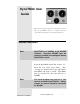
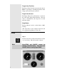
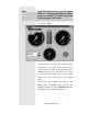
DynoTRAC Main Screen The main DynoTRAC interface screen is shown below.
File and Option pull-down menus File The exit program option can be found in the File pull-down menu. You can also exit the program by clicking the X button in the far upper right corner of the main screen. Option Click on Control to select a gauge. Click on Gauge to bring up the Gauge Configuration Window.
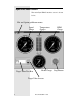
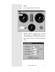
Target Value Text Box The Target Value Text Box represents the Speed, RPM or a percentage of braking dependent on the Gauge (mode) the user has selected. Target Value Arrows The Target Value Arrow will increase or decrease the value in the Target Value Text Box. The new value is determined by the Step Size for that particular gauge. Stop Button The Stop Button is used to set the brake to 100% braking. (The Space Bar on the computer keyboard will also toggle the Stop Button on and off.
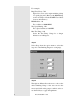
Step 2 Select Gauges from the option menu. Enter the values for “Plug Fires Every” and the “Tach Redline” for the RPM Gauge. Enter the “Tire Speed Rating” for the Speedometer Gauge. Enter “Max Tire Temp” for the Tire Temperature Gauge.
For example: Plug Fires Every: 720 Typical for a four cycle engine with the pickup on a spark plug wire. (Refer to the RPM Pickup section of Chapter 4 in the WinPEP User Guide for more information.) RPM Redline : 10 For a redline at 10,000 RPM. Tire Speed Rating: 120 For a Speed redline at 120 MPH. Max Tire Temp: 180 Scales the Tire Temp. Gauge for a danger indication at 180 degrees. Step 3 Select Steps from the option menu to select the step size of the Braking Target for each gauge.
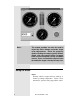
Note: DynoTRAC will maintain a specific speed, RPM, or % Braking, depending on which gauge is selected. The outer ring on the selected gauge will be white. For instance: RPM Use the mouse to click the Up or Down Target Value Arrow or use the up and down arrow keys on the keyboard or click on the guage directly to change the target value. The user can also select the select the value in the text box by double clicking the mouse and typing in the desired value.
Note: The remote pendant can also be used to select the Active Gauge and make target value adjustments. Select the gauge by double clicking the sample (green) button. Single click the sample button to toggle back and forth between the up and down arrows. Press and hold the sample button to modify the target value by the step size. Using the Brake Step 1 Start the vehicle’s engine and let it warm up to normal operating temperature. Verify correct tachometer operation and gauge redline values.
Put the vehicle in gear to begin the test. Shift up to the desired test gear and press the brake button on the Remote Pendant. As the target RPM is approached the brake will begin to engage. The amount or percentage of braking will depend on the power of the engine being tested and the test gear. Note: As a safety precaution, if you change modes (select another gauge) while the brake button is pressed, the current value in the gauge will be copied to the Target Value Text Box.
Brake Over Heating The DynoWare EX+ electronics continuously monitors the brake temperature. If the brake temperature approaches an unsafe limit, the brake gauge perimeter will begin flashing red. Should this occur, stop testing and allow the brake to cool to a normal operating temperature, as indicated by the temperature gauge. Warning!! If the brake temperature exceeds a safe operating limit, the brake will be deactivated.
Rev Limit From the option menu select “Rev Limit”. With this option enabled, if the engine reaches redline, DynoTRAC will be automatically apply full braking. When the engine RPM drops below redline, normal brake operation resumes. (This feature operates whether or not the pendant brake button is on.
Exiting DynoTRAC To exit the program: Bring the dyno to a complete stop. (This may be done by clicking on the stop button.) Select EXIT from the File menu and the program will close. Warning!! 12 Exiting DynoTRAC while the pendant brake button is on, will fully engage the brake.