
Manual


Torque Module Installation and User Guide for Model 250 Dynamometers
CHAPTER 2
Torque Cell Calibration
2-2
. . . . . . . . . . . . . . . . . . . . . . . . . . . . . . . . . . .
TORQUE CELL CALIBRATION
The Torque Module must be calibrated prior to use. Follow the directions on the
screen exactly. Failure to perform the directions accurately will result in improper
torque values.
1 Verify you are in the MakeRun screen.
2 Verify you are connected to the dyno electronics.
Note: For more information on connecting to the dyno electronics, refer to the
WinPEP 7 User Guide (on your WinPEP CD or at
www.dynojet.com/manuals.shtml) or the WinPEP 7 Online Help.
3Select Tools
MakeRun Options
Torque Cell Calibration.
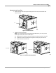
Note: Before proceeding, be sure the eddy current brake is free and clear of any
obstructions. There should not be anything resting on the eddy current brake or
the dynamometer drum during this procedure.
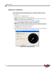
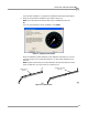
4Click Next to perform the Zero Calibration.
The Calibration window will appear. The hardware is now zeroing out the torque
cell. If the unit does not calibrate, recheck the setup and retry.
Figure 2-1: Zero Calibration Window