©2004 Dynojet Research, Inc. All Rights Reserved. Control Panel Interface Upgrade Installation Guide For Model 200i and 250i Motorcycle Dynamometers Serial Number 201xxxx. This manual is copyrighted by Dynojet Research, Inc., hereafter referred to as Dynojet, and all rights are reserved. This manual is furnished under license and may only be used or copied in accordance with the terms of such license.
April 12, 2004 Control Panel Interface upgrade for 200i/250i Dynos Serial Number 201xxxx These instructions are intended for use with installing the Control Panel Interface upgrade into Dynojet Research model 200i and 250i dynos with serial number 2011001 to 2011089. Before proceeding, check the serial number on the dyno front left corner to verify it is in this range. The Dynojet part number for this upgrade is 78121002.
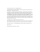
2. Once the covers are off, inspect your dyno to verify that the starter brace is installed. If your dyno does not have a starter brace, you will need to install the brace. Refer to version 3 of your dyno installation manual (P/N 98220104) pages 4-21 and 4-23. The starter brace supports the back of the starter and provides a good ground connection. Starter Brace 3. If a battery is installed, disconnect the negative terminal of the battery first then remove the positive terminal.
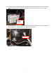
. Remove the power cable that connects from the Power Distribution assembly to the Theta Controller. The outer ring of this connector unscrews to release the connector. Leave the Theta Controller in place. Unscrew and pull this connector 6. Remove the power cable to the Stack Box from the back of the Stack Box. This connector plugs into the back of the box. You may need to cut cable ties to free the cord.
7. On the back of the Power Distribution assembly you will need to remove three cables. These cables will be re-used with the new Control Panel Interface/Power Distribution. Gently pull the quick lugs for the two fan cables from the backs of the two circuit breakers. Make sure to only pull on the quick lug and not on the wire. Loosen the barrier strip and remove the ground connections for the fan cables. Leave the rest of these cables in the dyno as they will be installed on the new hardware.
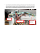
8. Disconnect the main dyno power cable. This is the large cable that provides all of the power into the dyno. Remove the two connections on the main breaker then the connection on the barrier strip. Remove the ground connection. Leave the rest of this cable in the dyno as it will be installed on the new hardware. 9.
10. Remove the four bolts holding the Power Distribution assembly and remove the old Power Distribution assembly. Remove these bolts 11. Disconnect the red battery cable from the starter and the black battery cable from the ground connection. Disconnect the starter solenoid wire also. All wires should be removed from the starter. Disconnect the red and black wires that go into the black box on the back wall of the drum module.
12. If the starter switch has been installed through one of the cable access holes, remove the cable access plate and feed the starter switch back into the dyno and coil up in the front inside of the dyno. This will not be used with the new hardware. 13. If your dyno has an air brake installed, trace the wires from the air brake solenoid to the black box. Cut the black solenoid wires at the point where the wires are extended to connect to the black box.
18. Carefully install the new Power Distribution assembly in the dyno from the inside of the dyno and attach with four ¼-20 x ½ -inch hex head bolts. Fasten with four ¼-20 x 1/2 -inch hex head bolts 19. Connect the power cable from the Power Distribution assembly to the back of the Stack Box. Replace the cable ties that were cut previously to form a bundle and service loop. You should still be able to remove the Stack Box when this bundle is complete. Connect the power cable to the Theta Controller.
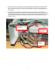
20. The main power cable needs to be re-installed to the new Power Distribution assembly. Connect the incoming power as follows: the brown wire to the left top screw on the 30A breaker – Connect the blue wire to the right top screw on the 30A breaker. Connect the black wire with the white tape to the top side of the DIN rail in the position 7th from the left. Fasten the green/yellow wire to the stud that is above and to the right of the DIN rail with a #8 nut with internal washer. Cable tie as shown.
21. Connect the right fan cable ground ring lug to the stud to the right of the top 15A circuit breaker with a #8 nut with internal lock washer. Connect the blue spade lug to the lower right lug of the top 15A breaker and the brown wire to the upper right lug. 22. Connect the left fan cable ground ring lug to the stud to the right of the bottom circuit breaker with a #8 nut with internal lock washer.
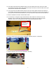
23. Route the wiring to the optional Wheel Clamp and Power Carriage through the dyno. You may find it easier to slide the Stack Box out of the side of the dyno and remove its support bracket for routing these cables. Even if you have not purchased these optional accessories it is better to install the cables now for an easy upgrade in the future. Remove bracket 24. Remove the front cable access plate.
25. Route the P/N 76950308 Pod to Carriage cable from P8 on the Control Panel Interface board to the front cable hole on the dyno. The cable passes under the center partition in the carriage module and in front of the vertical angle. Make sure that the cable strain relief end with the conduit nut is at the end of the cable that will connect to the carriage. The strain relief for both the Power Carriage and the Wheel Clamp must end up outside of the dyno. Strain relief 26.
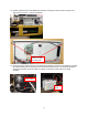
27. Re-Install the Stack Box support bracket with four ¼-20 x ½ -inch hex head bolts. Re-install the Stack Box and secure with four ¼-20 x ½ -inch hex head bolts. Support Bracket 28. Connect the P/N 76950403 Air Pump cable to P11 on the Control Panel Interface front side and route the cable out the rear hole on the Control Panel Interface to the back of the dyno.
29. Route the Air Pump cable out the back of the carriage module along the cable support bracket to the back of the dyno and across the back of the dyno to the Air Pump. Do not cable tie yet as there are more cables to add to the bundle. The 4 pin connector on the Air Pump cable is designed to plug right into the Air Pump. Your Air Pump may have been built before the matching connector was normally put on in production.
30. Install the Breakout board back into its standard location as shown and connect the 25 pin cable. 31. If you have an air brake, install P/N 76950110 cable into P7 in the Control Panel Interface board and run the short cable to the Breakout board as shown and connect. Cable tie as shown and route the other end to the air brake solenoid. Strip back the wires to the brake air solenoid and crimp into the barrel connections on the P/N 76950110 Air Brake cable.
32. Route the wire harness to the Control Panel assembly. Depending on the location of the monitor upright, the wire harness can be routed to either side of the dyno. The P/N 76951501 cable plugs in the Control Panel Interface Board P4. This cable should be cable tied to the Power Distribution assembly to make sure the cable does not pull on the board. Cable tie here P4 33. If you do not have a monitor tray and stand it will be necessary to purchase one from Dynojet to mount the Control Panel assembly.
34. Early production Monitor Arms, uprights, and the monitor tray may not have the tapped holes for routing the Control Panel cables and mounting the Control Panel. If your monitor stand arms do not have these holes, it will be necessary for you to drill and tap the holes in the monitor upright and the arms to allow for attaching the Control Panel cable bundle. The cable bundle needs to be arranged across the monitor arms to allow for easy movement of the monitor stand without pulling on the cables.
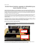
35. The Control Panel needs to be disassembled so the cable to the Control Panel Interface can be connected. Remove the screw and nuts shown and lift off the back/side cover.
36. Connect the Control Panel cable to the Control Panel Button board. Cable tie the incoming cable as shown. Cable tie here 37. Replace the Control Panel cover with the hardware that you removed before.
38. Mount the Control Panel to the side of the monitor tray. The cable lengths are set to allow installing the Control Panel on either side of the monitor tray for easy access. Route the cable bundle along the arms with service loops to allow movement. Make sure that during normal arm movement the cable does not get pinched.
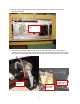
39. The battery cables and starter cables need to be connected next. The 4 pin connector plugs into the back side of the Control Panel Interface board near the middle of the board to P2. The cable routes out of the back of the Power Distribution assembly as shown.
40. Install the starter support brace, if necessary, and then connect the other end of the battery cables to the starter as shown.
41. Route the cables to the cable support bracket as shown. Cable tie as shown. Make sure all of the cables clear any moving components. Only connect the positive terminal on the battery at this time. If this is the first time you have installed a battery in this dyno refer to the dyno install guide for instructions on installing the battery hold down bracket.
42. If you purchased either the Wheel Clamp or the Motorized Carriage, position the Motorized Carriage motor and/or the Wheel Clamp close to the dyno and plug in their motor cables for testing.
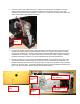
43. If you have an air brake and your dyno room is equipped with a safety switch on the door, it is necessary to connect the safety switch to the Control Panel Interface board interlock input to apply the air brake whenever the dyno room door is open. Connect the wires feeding the switch contacts to Interlock 1-A and Interlock 6-B connection points on the Control Panel Interface board. The board is shipped with a jumper wire in this location.
45. Turn on the main breaker on side of the dyno by moving it to the up position. Make sure the E-Stop button on the Control Panel is in the out position. Twist if necessary to take it out of E-Stop. Turn on the switch on the front of the Stack Box. 46. If you have the optional High Speed Blowers, verify they are plugged in to the sides of the dyno then press the fan control buttons on the Control Panel and verify that the fans turn on and off. Press once to turn on and once to turn off. 47.
48. If you purchased the optional Wheel Clamp then press the left hand clamp button and verify that the Wheel Clamp closes. Release the button. Press the right hand clamp button first then press the left hand clamp button and hold both buttons to open the clamp. Refer to the user’s manual for more details of the operation. 49. If you purchased the optional Motorized Carriage then press the carriage forward and back buttons and verify carriage movement.
51. Replace the door on the front side of the Control Panel Interface/Power Distribution box with the 6-32 x ½ -inch screw hardware that you removed to take off the door. Reinstall the door stop chain with the two 8-32 nuts. 52. Put the carriage module cover back on. Put the drum and retarder module covers back on. Install the carriage. 53. Plug the dyno power cable in and turn on the main breaker on the power distribution assembly. Turn on the power switch on the front of the Stack Box.