
Installation Guide Owner's manual


In Ground Model 200iP/250iP Motorcycle Dynamometer Installation Guide
APPENDIX C
Door Safety Switch
C-4
. . . . . . . . . . . . . . . . . . . . . . . . . . . . . . . . . . .
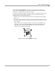
DOOR SAFETY SWITCH
Safety requirements of your local country may require that a door safety switch is
installed. Be sure to follow the safety requirements specific to your country. The door
safety switch requires the air brake to work. This switch is located on the dyno room
door and is triggered when the pressure applied to it is released causing the air brake
to lock. This prevents the dyno from being used when the door is open.
Components attached to and within the dynamometer operate with potentially
lethal voltages. To provide the greatest assurance of safety, the AC power
cord(s) must be disconnected from the power source before servicing electrical
components or wiring. Disconnect all power cords before servicing electrical
components for the greatest assurance of safety.
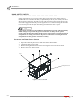
INSTALLING THE DOOR SAFETY SWITCH
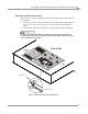
1 Open the CPI front panel access and turn off the main breaker.
2 Unplug the dyno power cable.
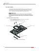
3 Remove the eight button-head screws securing the CPI cover and set aside.
4 Remove the cover and set aside.
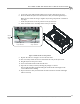
Figure C-3: Access the CPI
PD027
cover
front panel access