
Installation Guide User guide

Model 200iP/250iP Motorcycle Pit Dynamometer Installation Guide
CHAPTER 2
Routing Cables
2-32
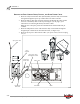
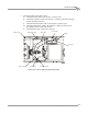
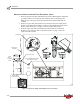
ROUTING THE EDDY CURRENT BRAKE, BATTERY, AND DYNO POWER CABLES
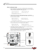
1 Route the eddy current brake cable (P/N 66952005) from the eddy current brake
through the designated power pit conduit and to the theta controller.
2 Route the battery cable (P/N 76950312) from the CPI through the same conduit
and over to the battery. Refer to the steps and Figure 2-35 on page 2-33 for
instructions on connecting the battery and starter cables.
Note: Be sure to keep the power and communications cables in different pit
conduits.
3 Route the temperature sensor cable from the eddy current brake through the
designated pit conduit and to the break-out board, see Figure 2-38.
4 Route the dyno power cable from the CPI to your power source, but do not plug
it in yet.
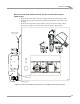
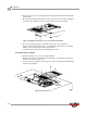
Figure 2-34: Route the Eddy Current Brake, Battery, and Power Cables
PD034
C
battery cable
dyno power cable
CPI
eddy current
brake cable
battery
dyno
electronics
route power cables
in designated conduit
starter
starter cable
theta
controller
temperature
sensor cable