©2008-2012 Dynojet Research, Inc. All Rights Reserved. Extended Carriage with Trike Adapter Assembly Installation Guide for Model 200iX/250iX Dynamometers This manual is copyrighted by Dynojet Research, Inc., hereafter referred to as Dynojet, and all rights are reserved. This manual, as well as the software described in it, is furnished under license and may only be used or copied in accordance with the terms of such license.
TABLE OF CONTENTS Extended Carriage with Trike Adapter Assembly Installation Introduction . . . . . . . . . . . . . . . . . . . . . . . . . . . . . . . . . . . . . . . . . . . . . . . . . . . 2 Conventions Used In This Manual . . . . . . . . . . . . . . . . . . . . . . . . . . . . . . . . Technical Support . . . . . . . . . . . . . . . . . . . . . . . . . . . . . . . . . . . . . . . . . . . . Trike Carriage Adapter Installation . . . . . . . . . . . . . . . . . . . . . . . . . . . . . . . .
EXTENDED CARRIAGE WITH TRIKE ADAPTER ASSEMBLY INSTALLATION This document provides instructions for installing the extended carriage with the trike adapter assembly on the model 200iX and 250iX motorcycle dynamometers (dyno). To ensure safety and accuracy in the procedures, perform the procedures as they are described.
E X T E N D E D C A R R I A G E W I T H TR I K E A D A P T E R A S S E M B L Y I N S T A L L A T I O N Introduction INTRODUCTION ................................... Use the following instructions to remove the carriage assembly, install the extended support (P/N 78100003), install the trike carriage adapter (P/N 71300002), and install the extended carriage assembly. CONVENTIONS USED IN THIS MANUAL The conventions used in this manual are designed to protect both the user and the equipment.
E X T E N D E D C A R R I A G E W I T H TR I K E A D A P T E R A S S E M B L Y I N S T A L L A T I O N Trike Carriage Adapter Installation TRIKE CARRIAGE ADAPTER INSTALLATION ................................... Use the following instructions to remove the carriage assembly, install the extended support (P/N 78100003), install the trike carriage adapter (P/N 71300002), and install the extended carriage assembly.
E X T E N D E D C A R R I A G E W I T H TR I K E A D A P T E R A S S E M B L Y I N S T A L L A T I O N REMOVING THE CARRIAGE SCREW AND CARRIAGE The monitor stand and high pressure blowers are not shown for clarity. If the carriage is not installed, skip to “Installing the Extension Support and Trike Carriage Adapter Assembly” on page 6. 1 2 3 Remove the four 1/4-20 x 1/2-inch button-head screws securing the bearing bracket and set aside.
E X T E N D E D C A R R I A G E W I T H TR I K E A D A P T E R A S S E M B L Y I N S T A L L A T I O N Trike Carriage Adapter Installation REMOVING THE CARRIAGE CLAMPS, SHIMS, AND NUT BLOCK If the carriage is not installed, skip to “Installing the Extension Support and Trike Carriage Adapter Assembly” on page 6. 1 2 3 4 Remove the two 5/16 x 1-inch bolts and two 5/16-inch lock washers securing each carriage clamp and shim and discard. This hardware will not be used.
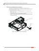
E X T E N D E D C A R R I A G E W I T H TR I K E A D A P T E R A S S E M B L Y I N S T A L L A T I O N INSTALLING THE EXTENSION SUPPORT AND TRIKE CARRIAGE ADAPTER ASSEMBLY 1 2 Secure the left and right brackets to the extension support brace mount using two 3/8 x 1-inch hex bolts and two 3/8-16 nylock nuts each. Secure each leveling mount using two 3/8-inch nuts.
E X T E N D E D C A R R I A G E W I T H TR I K E A D A P T E R A S S E M B L Y I N S T A L L A T I O N Trike Carriage Adapter Installation 3 Secure the extension support to the dyno using five 3/8 x 1/2-inch button-head flange bolts. 4 Secure the extension support brace to the extension support and the dyno using two 3/8 x 1/2-inch button-head flange bolts. Use the leveling mounts to make the support brace snug against the floor. Tighten the nuts to secure the leveling mounts.
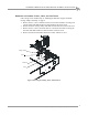
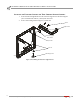
E X T E N D E D C A R R I A G E W I T H TR I K E A D A P T E R A S S E M B L Y I N S T A L L A T I O N 7 Secure the trike carriage adapter assembly to the dyno and the extended support using five 5/16 x 1-inch button-head bolts as shown in Figure 5. 8 Secure the trike carriage adapter assembly to the dyno and the extended support using two 3/8 x 1-inch button-head bolts as shown in Figure 5. Lube the tracks with the included lube or use grease.
E X T E N D E D C A R R I A G E W I T H TR I K E A D A P T E R A S S E M B L Y I N S T A L L A T I O N Trike Carriage Adapter Installation INSTALLING THE EXTENDED CARRIAGE ASSEMBLY 1 2 3 4 If not already removed, remove the carriage screw from the extended carriage assembly by removing the four 1/4-20 x 1/2-inch button-head screws securing the bearing bracket and set aside. Place the carriage screw with the bearing bracket into the nut block.