©2008-2012 Dynojet Research, Inc. All Rights Reserved. Installation Guide For In Ground Model 200iPX and 250iPX Motorcycle Dynamometers. This manual is copyrighted by Dynojet Research, Inc., hereafter referred to as Dynojet, and all rights are reserved. This manual is furnished under license and may only be used or copied in accordance with the terms of such license.
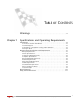
TABLE OF CONTENTS Warnings Chapter 1 . . . . . . . . . . . . . . . . . . . . . . . . . . . . . . . . . . . . . . . . . . . . . . . .vii Specifications and Operating Requirements Introduction . . . . . . . . . . . . . . . . . . . . . . . . . . . . . . . . . . . . . . . . . . . . . . . . . . 1-2 Conventions Used In This Manual . . . . . . . . . . . . . . . . . . . . . . . . . . . . . . . 1-3 Technical Support . . . . . . . . . . . . . . . . . . . . . . . . . . . . . . . . . . . . . . . . . . .
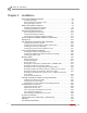
TA B L E O F C O N T E N T S Chapter 2 Installation Dyno Drum Module Installation . . . . . . . . . . . . . . . . . . . . . . . . . . . . . . . . . 2-2 Unpacking the Dyno . . . . . . . . . . . . . . . . . . . . . . . . . . . . . . . . . . . . . . . . . 2-2 Removing the Dyno from the Crate . . . . . . . . . . . . . . . . . . . . . . . . . . . . . . 2-7 Placing the Dyno in the Pit . . . . . . . . . . . . . . . . . . . . . . . . . . . . . . . . . . . . 2-8 Eddy Current Brake Installation . . . . . . . . . .
TA B L E O F C O N T E N T S Chapter 3 Accessories Main Dyno Power . . . . . . . . . . . . . . . . . . . . . . . . . . . . . . . . . . . . . . . . . . . . . 3-2 Air Brake . . . . . . . . . . . . . . . . . . . . . . . . . . . . . . . . . . . . . . . . . . . . . . . . . . . . . 3-3 Routing the Air Brake Cable and Air Hose . . . . . . . . . . . . . . . . . . . . . . . . . . 3-3 Installing the Emergency Stop Sticker . . . . . . . . . . . . . . . . . . . . . . . . . . . .
TA B L E O F C O N T E N T S Appendix A Red Head Anchor Installation Warnings . . . . . . . . . . . . . . . . . . . . . . . . . . . . . . . . . . . . . . . . . . . . . . . . . . . . .A-1 Contact Information for ITW Ramset/Red Head . . . . . . . . . . . . . . . . . . . . .A-1 Installation . . . . . . . . . . . . . . . . . . . . . . . . . . . . . . . . . . . . . . . . . . . . . . . . . . .A-2 Appendix B Power Requirements and Installation Locations Using 60 Hz Power (North America and Japan) . . . . . . . .
WARNINGS Disclaimers Dynojet Research, Inc. (Dynojet) makes no representation or warranties with respect to the contents hereof and specifically disclaims any implied warranties of merchantability for any particular purpose. Dynojet reserves the right to revise this publication and to make changes from time to time in the content hereof without obligation of Dynojet to notify any person of such revision or changes.
WA R N I N G S Electrostatic Discharge Precautions Electrostatic Discharge Electrostatic Discharge (ESD), or static shock, can damage electronic components within the dynamometer. The damage may occur at the time of an ESD occurrence, or the shock may degrade the component, resulting in a premature component failure later. To avoid ESD damage, always practice good ESD control precautions when servicing the dynamometer.
WA R N I N G S Other Potential Hazards The AC power outlet shall be installed near the equipment and it shall be easily accessible to allow for disconnect before service. The dynamometer should be located in a well ventilated area. There is a carbon monoxide hazard with all internal combustion engines. Engine exhaust contains poisonous carbon monoxide gas. Breathing it could cause death. Any dyno room design must incorporate sufficient exhaust extraction.
CHAPTER 1 SPECIFICATIONS AND OPERATING REQUIREMENTS Thank you for purchasing Dynojet’s In Ground Model 200iPX/250iPX Motorcycle Dynamometer. Dynojet’s software and dynamometers will give you the power to get the maximum performance out of vehicles you evaluate. Whether you are new to the benefits of a chassis dynamometer or an experienced performance leader, the repeatability and diagnostic tools of WinPEP 7 software and a Dynojet dynamometer will give you the professional results you are looking for.
CHAPTER 1 Introduction INTRODUCTION ................................... Before installing your dyno, please take a moment to read this guide for installation instructions, dyno features, and other important information. This guide is designed to be a reference tool in your everyday work and includes the following chapters and information: SPECIFICATIONS AND OPERATING REQUIREMENTS This chapter describes the requirements and specifications for the dyno.
SPECIFICATIONS AND OPERATING REQUIREMENTS Introduction CONVENTIONS USED IN THIS MANUAL The conventions used in this manual are designed to protect both the user and the equipment. example of convention RECORD # Bold description The Caution icon indicates a potential hazard to the dynamometer equipment. Follow all procedures exactly as they are described and use care when performing all procedures.
CHAPTER 1 Introduction YOUR DYNO ROOM This section is not meant to imply that a dyno room is essential to repeatable results on a Dynojet dynamometer. However, a dyno room with an engine cooling intake fan, exhaust extraction, and noise reduction capabilities can add a new dimension to your shop. A proper dyno room design will help to ensure repeatable, accurate runs.
SPECIFICATIONS AND OPERATING REQUIREMENTS Dynamometer Specifications and Requirements DYNAMOMETER SPECIFICATIONS AND REQUIREMENTS ................................... The following specifications and requirements will help you set up your dyno area and verify you have the requirements to operate your dyno safely. BATTERY REQUIREMENTS Your 200iPX/250iPX dyno is designed to carry a group 24 deep-cycle discharge series battery for operating the starter, power carriage, and optional wheel clamp.
CHAPTER 1 Dynamometer Specifications and Requirements standard carriage 304.80 cm (120.00 in.) extended carriage 355.60 cm (140.00 in.) 137.16 cm (54.00 in.) 45.72 - 46.67 cm (18.00 - 18.38 in.) PD189 239.00 cm (91.10 in.) pit covers 310.29 cm (122.16 in.) including eddy current brake cover 273.30 cm (107.60 in.) 76.20 cm (30.00 in.
SPECIFICATIONS AND OPERATING REQUIREMENTS Dynamometer Specifications and Requirements Monitor Support and Tray Control Panel Wheel Clamp Option Power Carriage Control Panel Interface Trike Adapter Assembly houses all electronics (not shown) PD105 High Pressure Blower Air Brake Option Eddy Current Brake Model 250iP Dyno Module (not shown) Air Pump Option iPX Drum Module (not shown) Figure 1-2: Model 250iPX Dyno with Accessories Version 3 In Ground Model 200iPX/250iPX Motorcycle Dynamometer In
CHAPTER 1 Dynamometer Specifications and Requirements COMPRESSED AIR REQUIREMENTS The following requirements are needed when the optional air brake is included. • regulator set to 65 psi max (450 kilopascal) • air dryer • shut off valve • gauge on the regulator • 1/4-inch NPT pipe thread connector (to attach air to the dyno) COMPUTER SPECIFICATIONS You will need to provide a computer system to run the WinPEP software. WinPEP 7 includes complete documentation in online Help.
SPECIFICATIONS AND OPERATING REQUIREMENTS Dynamometer Specifications and Requirements GROUND HOOK REQUIREMENTS You may wish to install additional ground hooks (included with your dyno) for securing the motorcycle. The tie-down loops on the pit covers should work for most motorcycles. If you are running motorcycles that require a different tie-down location, mount the ground hooks accordingly. Note: Tie-down straps MUST pull the motorcycle forward.
CHAPTER 1 Dyno Electronics DYNO ELECTRONICS ................................... The standard dyno electronics package is comprised of four interconnected modules: Atmospheric Sensing Module, RPM Module, Dynamometer Input/Output Module, and the CPU Module. For more information refer to your WinPEP 7 User Guide (P/N 98128104).
SPECIFICATIONS AND OPERATING REQUIREMENTS Verify the Pit Dimensions VERIFY THE PIT DIMENSIONS ................................... Before placing the dyno in the pit, take a moment to verify that the dimensions of the pit are correct. Refer to the pit dimensions (P/N 98229104) you received from your salesman for more detailed specifications. • pit depth: 45.00 cm (18.00 in.) • pit length: 294.64 cm (116.00 in.) • pit width: 121.00 cm (48.00 in.) 121.00 cm (48.00 in.) 294.64 cm (116.00 in.
CHAPTER 2 INSTALLATION This chapter will walk you through unpacking and installing the dynamometer. To ensure safety and accuracy in the procedures, perform the procedures as they are described.
CHAPTER 2 Dyno Drum Module Installation DYNO DRUM MODULE INSTALLATION ................................... When you receive your dyno, examine the exterior of the shipping container for any visible damage. If damage is detected at this stage, contact the shipper or Dynojet before proceeding with unpacking. Use the following steps to unload your dyno. You will need to provide equipment capable of lifting a minimum of 1,089 kg. (2400 lb.) to move the crated dyno into position in your dyno room.
INSTALLATION Dyno Drum Module Installation 5 part Version 3 Verify the contents of the hardware boxes and set aside.
CHAPTER 2 Dyno Drum Module Installation part description cable junction box cover P/N 21228521 part description generic i dyno, pit P/N 62919003 drum guard, side (2) P/N 21229111 retarder module, pit P/N 62919004 drum guard mounting bracket P/N 21624103 tire stop P/N 63310902 cable track mounting bracket P/N 21626217 control panel button subassembly P/N 66117001 cable track adapter bracket P/N 21626218 wheel clamp P/N 71329000 not included if you ordered the optional wheel clamp optional acces
INSTALLATION Dyno Drum Module Installation part description screw, 8-32 x 3/8", pan-head, phil (30) P/N 36540643 screw, 1/4-20 x 5/8", panhead, torx (12) P/N 36561045 part description iPX upgrade kit P/N 77000004 shipped in a separate crate, refer to page 2-12 standard carriage P/N 78100004 or extended carriage P/N 78100005 Version 3 bolt, 3/8-16 x 1/2", buttonhead, flange, allen (16) P/N 36580434 ground hook kit (2) P/N 79190001 washer, 3/8", splitlock, steel (12) P/N 36932100 power carriage P/N
CHAPTER 2 Dyno Drum Module Installation part description cable clamp, 5/8" (7) P/N 43428232 part cable track P/N 43432150 description bolt, 3/8-16 x 1", hex (12) P/N DM150-019-012 nut, crush, 1/4-20 (8) P/N DM150-020-005 cable track mounting bracket P/N 43432151 The following parts are included in the Retarder Module, Pit P/N 62919004: pit cover, plate, retarder P/N 21226106 theta-2 controller-240V P/N 66411003 retarder driveline assembly P/N 62240070 temperature probe assembly P/N 76955001 The
INSTALLATION Dyno Drum Module Installation REMOVING THE DYNO FROM THE CRATE This section will walk you through removing the dyno from the crate and installing the dyno in your pit. You will need to provide equipment capable of lifting a minimum of 1,089 kg. (2400 lb.) to lift the dyno (drum module) off the crate and into position in your dyno room. You will also need a pair of straps capable of supporting 1,089 kg. (2400 lb.) to attach to the dyno. Dynojet recommends using a single loop style strap.
CHAPTER 2 Dyno Drum Module Installation PLACING THE DYNO IN THE PIT Place the drum module in the pit as shown in Figure 2-3. Note: Figure 2-3 shows drum placement for an eddy current brake. 15.24 cm (6.00 in.) PD107 105.41 cm (41.50 in.
INSTALLATION Eddy Current Brake Installation EDDY CURRENT BRAKE INSTALLATION ................................... This section will walk you through removing the eddy current brake (or retarder) from the crate and attaching the brake to your dyno. To route and wire the temperature sensor cable and the theta controller to the Breakout board refer to “Routing the Eddy Current Brake, Battery, and Dyno Power Cables” on page 2-39 and “Wiring the Breakout Board” on page 2-43.
CHAPTER 2 Eddy Current Brake Installation INSTALLING THE EDDY CURRENT BRAKE 1 2 Insert the key into the keyway on the drum module shaft. Use a c-clamp to press the key in.
INSTALLATION Eddy Current Brake Installation 3 4 5 6 7 8 9 Remove the eight bolts, washers, and six nuts from the dyno frame where the connector plates will attach (where the connector plate attaches to the starter brace, there are only two nuts). Remove the starter brace and set aside. Keeping the panels parallel, slide the eddy current brake towards the dyno. Slide the driveline assembly over the key on the dyno shaft.
CHAPTER 2 iPX Drum Module Installation IPX DRUM MODULE INSTALLATION ................................... When you receive your iPX upgrade kit, examine the exterior of the shipping container for any visible damage. If damage is detected at this stage, contact the shipper or Dynojet before proceeding with unpacking. Use the following steps to unload the iPX drum module and related items. You will need to provide equipment capable of lifting a minimum of 363 kg. (800 lb.
INSTALLATION iPX Drum Module Installation part description bolt, 3/8-16 x 1/2", buttonhead, flange, allen (6) P/N 36580434 woodruff key, 3/8 x 1-3/8" P/N 37620622 part description ground hook kit (4) P/N 79190001 see list of parts below nut, crush, 1/4-20 (4) P/N DM150-020-005 The following parts are included in each Ground Hook Kit P/N 79190001: 4 5 Version 3 ground hook/D-ring P/N 10111 anchor, redhead, 3/8" (2) P/N 37513200 D-ring bracket, surface mount P/N 10112 washer, 5/16", flat (2) P/N
CHAPTER 2 iPX Drum Module Installation INSTALLING THE IPX DRUM MODULE You will need the following parts: 1 2 3 4 5 6 7 8 • 37620622 Woodruff Key (2) • 62200004 Driveline Assembly • 63200002 iPX Drum Module Place the nylon loop strap around the shaft on either side of the drum module. Remove the two existing screws from each side of the dyno frame where the connector plates will attach. Insert the woodruff key into the keyway on the drum module shaft.
INSTALLATION iPX Drum Module Installation 9 10 11 12 13 Secure the connector plate on either side of the iPX drum module to the dyno drum module using the bolts removed earlier. Loosen the four bolts on either side of the iPX drum module as shown in Figure 2-8. Align the iPX drum module panels until they are flush with the top of the pit floor and the dyno drum module panels. Once you have verified the panels are flush and parallel, tighten all the screws. Tighten the driveline set screws.
CHAPTER 2 iPX Drum Module Installation LINING UP AND SECURING THE MODULE UPRIGHTS 1 2 3 Verify the uprights on the drum and eddy current brake modules are flush with the top of the pit floor before you tighten the connector plates. 1a Loosen all upright bolts. 1b Place two straight edges across the drum module uprights. 1c With the upright tight against the straight edges and flush with the pit floor, tighten the connector plate bolts and nuts on the drum module.
INSTALLATION Secure the Drum and Brake Module to the Pit Floor SECURE THE DRUM AND BRAKE MODULE TO THE PIT FLOOR ................................... Dynojet recommends you secure your drum and brake modules to the pit floor in your dyno room using concrete anchors. You will want to drill the holes and secure the dyno before placing the covers on your dyno. Note: You may wish to drill the holes for the left and right blower mounts along with the trike adapter mounting plate this time.
CHAPTER 2 Pickup Card PICKUP CARD ................................... The pickup card is an electronic circuit board that accurately senses each drum revolution. 1 2 3 4 5 Locate the pickup card bracket on the starter side of the dyno just ahead of the drum. Install the pickup card to the bracket using two No. 8 screws. Do not tighten, the card must be aligned first.
INSTALLATION Left Side Blower and Monitor Arm Installation LEFT SIDE BLOWER AND MONITOR ARM INSTALLATION ................................... Use the following instructions to install the left side blower mount, monitor support, and junction box along with the left blower assembly and monitor tray. The right blower mount and assembly will be installed later.
CHAPTER 2 Left Side Blower and Monitor Arm Installation INSTALLING THE LEFT BLOWER MOUNT If this is an iX upgrade to an existing 200iP/250iP dyno, skip these instructions and refer to Appendix E for upgrade instructions. 1 2 3 Mark the left blower mount placement as shown in Figure 2-12. Using the blower mount as a template, mark and drill the four holes needed to secure the blower mount to the floor. Install the Red Head anchors. Refer to Appendix A for installation instructions. 184.05 cm (72.46 in.
INSTALLATION Left Side Blower and Monitor Arm Installation INSTALLING THE MONITOR SUPPORT AND THE JUNCTION BOX 1 2 Place the blower mount where you installed the Red Head anchors on page 2-20. Secure the blower mount, monitor support arm, and junction box to the pit floor using four 3/8 x 1-inch bolts and four washers. Note: The left blower mount is secured under the support arm. 3 4 Verify the blank plate is secured to the junction box as shown in Figure 2-13.
CHAPTER 2 Left Side Blower and Monitor Arm Installation INSTALLING THE LEFT BLOWER ASSEMBLY 1 2 3 4 5 6 7 8 9 Insert a plastic cap in both ends of each arm. Place one 1/4-inch thick poly washer around the pin on the blower mount. Place the lower blower arm over the blower mount pin. Place a 3/8-inch thick metal washer on top of the lower blower arm. Secure the lower blower arm using the clamp lever. Place a 1/8-inch thick poly washer around the pin on the upper blower arm.
INSTALLATION Left Side Blower and Monitor Arm Installation INSTALLING THE MONITOR ARMS AND MONITOR TRAY 1 2 3 4 5 Insert a plastic cap in both ends of each arm. Place a poly washer around the pin of the first arm and insert the pin into the support arm. Place a poly washer around the pin of the second arm and insert the pin into the first arm. Place a poly washer around the pin of the tray and insert the pin into the second arm. Note: The monitor tray is an optional accessory.
CHAPTER 2 Trike Carriage Adapter Installation TRIKE CARRIAGE ADAPTER INSTALLATION ................................... Use the following instructions to install the trike carriage adapter plate, right blower assembly, and the cable track. The installation instructions are the same for both the standard and the extended carriage; verify you use the correct dimensions for the type of carriage you are installing.
INSTALLATION Trike Carriage Adapter Installation INSTALLING THE RIGHT BLOWER MOUNT AND BLOWER ASSEMBLY You will need the following parts: 1 2 3 4 • 21600015 Lower Blower Arm • 26215220 Washer, 3/8", Metal • 26215520 Washer, 1/8", Poly (2) • 26215521 Washer, 1/4", Poly (2) • 35521420 Cap Plug (4) • 35712991 Clamp Lever • 37513200 Anchor, Redhead, 3/8" (4) • 61328101 Blower Assembly • 61329601 Blower Mount • 63413001 Upper Blower Arm • DM150-002-007 Washer, 5/16", Flat (4) • DM150-019-012 Bolt, 3/8-16 x 1"
CHAPTER 2 Trike Carriage Adapter Installation 5 6 7 8 9 10 11 12 13 Insert a plastic cap in both ends of each arm. Place two 1/4-inch thick poly washers around the pin on the blower mount. Place the lower blower arm over the blower mount pin. Place a 3/8-inch thick metal washer on top of the lower blower arm. Secure the lower blower arm using the clamp lever. Place a 1/8-inch thick poly washer around the pin on the upper blower arm. Insert the pin on the upper arm into the lower arm.
INSTALLATION Trike Carriage Adapter Installation INSTALLING THE CABLE TRACK You will need the following parts: 1 2 • 134260301 Nut, 4-40, Hex (4) • 136206141 Screw, 4-40 x 3/8", Flat-Head (4) • 21200069 Cable Track Mounting Bracket, to Trike Adapter Assembly • 21626217 Cable Track Mounting Bracket • 43432150 Cable Track Remove the two 5/16-inch bolts and washers securing the carriage clamp as shown in Figure 2-19.
CHAPTER 2 Trike Carriage Adapter Installation 3 4 Secure the cable track to the mounting bracket on the trike adapter assembly using two 4-40 x 3/8-inch screws and two 4-40 nuts. Secure the cable track mounting bracket to the cable track using two 4-40 x 3/8-inch screws and two 4-40 nuts.
INSTALLATION Routing Cables ROUTING CABLES ................................... The CPI and dyno electronics must be placed near the conduits in the pit. Be sure to keep the power and communications cables in different pit conduits. For the following instructions, we will designate the pit conduits as shown in Figure 2-21.
CHAPTER 2 Routing Cables BATTERY REQUIREMENTS The model 200iPX/250iPX dyno is designed to carry a group 24 deep cycle discharge series battery for operating the starter, optional power carriage, and optional wheel clamp. The typical dimensions for this series of batteries are 10 5/8-inches long by 6 3/4-inches wide by 9 1/8-inches tall. The mounting is flexible so a battery that has dimensions close to this will work satisfactorily. The built in battery cables are configured for top post batteries.
INSTALLATION Routing Cables INSTALLING THE BATTERY 1 2 Secure the battery to the tray with the battery hold-down. Refer to page 2-39 for instructions on routing and connecting the battery cable.
CHAPTER 2 Routing Cables ACCESSING THE CPI The CPI comes wired and ready to install. Should you need to re-route the cables so they come out a different side of the box, use the following instructions to access the CPI box. 1 2 3 4 Turn off the power to the dyno. Refer to “Main Dyno Power” on page 3-2 for more information. Remove the eight button-head screws securing the cover and set aside. Remove the cover and set aside. Open the front panel to access the breakers and Breakout board.
INSTALLATION Routing Cables ROUTING THE CONTROL PANEL, PENDANT CABLES, AND RPM CABLE 1 2 Route the control panel cable (P/N 76951502) from the CPI through the designated communications pit conduit, through the pit, and out of the pit as shown. Route the pendant cable from the dyno electronics input/output module through the same conduit and along the same path as the control panel cable. Refer to “Dyno Electronics” on page 1-10.
CHAPTER 2 Routing Cables 5 Remove the control panel rear cover. 5a Remove the two nuts from the top of the cover and set aside. 5b Remove the screw on the top of the cover and set aside. 5c Remove the screw on the side of the cover and set aside. 5d Remove the four screws on the back of the cover and set aside. 5e Remove the control panel rear cover and set aside.
INSTALLATION Routing Cables 6 7 8 Route the control panel cable and RPM cable through the access hole on the side of the control panel box and through the cable tie. Attach the control panel cable to the Button board. Secure the panel mount connector on the RPM cable to the control panel using two #4-40 pan-head phillips screws. Note: Routing the RPM cable is optional.
CHAPTER 2 Routing Cables 12 Secure the control panel to the monitor tray using two 8-32-inch screws. Note: If you did not order a monitor tray, you will need to install the control pod spindle on the bottom of your control panel using four 8-32 screws as shown in the detail in Figure 2-28. Once installed, place the pin on the control panel into the support arm where the monitor tray is. 13 Place the pendant in the slot on the control panel.
INSTALLATION Routing Cables ROUTING THE HIGH PRESSURE BLOWER CABLES The high pressure blowers are an optional accessory. If you did not order the high pressure blowers it is still necessary to route the blower cables to the junction box. 1 Route each blower cable (P/N 76950315) from the CPI through the designated power pit conduit, through the pit, and out of the pit as shown. Note: Be sure to keep the power and communications cables in different pit conduits.
CHAPTER 2 Routing Cables ROUTING THE POWER CARRIAGE AND WHEEL CLAMP CABLES The wheel clamp is an optional accessory. After you install the wheel clamp you can finish routing the cables, refer to “Wheel Clamp” on page 3-17 for installation instructions. If you did not order this accessory, it is still necessary to route the cable to the junction box.
INSTALLATION Routing Cables ROUTING THE EDDY CURRENT BRAKE, BATTERY, AND DYNO POWER CABLES 1 2 3 4 Route the eddy current brake cable (P/N 66952005) from the eddy current brake through the designated power pit conduit and to the theta controller. Route the battery cable (P/N 76950312) from the CPI through the same conduit and over to the battery. Refer to the steps and Figure 2-32 on page 2-40 for instructions on connecting the battery and starter cables.
CHAPTER 2 Routing Cables 5 Connect the battery and starter cables. Be sure to route the cables through the cable routing bracket. Secure the cables to the bracket using cable ties. 5a 5b 5c 5d 5e battery cable Attach the brown cable to the positive (+) battery post. Attach the red battery cable to the positive (+) battery post and to the large stud on the starter solenoid. Attach the blue and yellow cable to the negative (-) battery post.
INSTALLATION Routing Cables ROUTING THE PICKUP CARD AND DYNO ELECTRONICS CABLES 1 Route the pickup card cable (P/N 66953002) from the CPI through the designated pit conduit and over to the pickup card. Attach the cable to the pickup card. Note: Be sure to keep the power and communications cables in different pit conduits. 2 Route the 25-pin cable (P/N 42924251) from the dyno electronics input/output module to the Breakout board. Refer to Figure 2-35 for Breakout board location.
CHAPTER 2 Routing Cables ROUTING THE AIR PUMP POWER, AIR FUEL SENSOR, AND DYNO ELECTRONICS POWER CABLES 1 2 3 Route the air pump power cable (P/N 76950318) from the CPI to the air pump. Route the air fuel sensor cable (P/N 76950701) from the dyno electronics to the air pump. Route the dyno electronics power cable to your power source. Refer to “Dyno Electronics” on page 1-10 for the dyno electronics power cable location.
INSTALLATION Routing Cables WIRING THE BREAKOUT BOARD 1 Attach the temperature sensor cable to the Breakout board. The temperature sensor cable has five wires which connect to the wiring block labeled TEMP. This cable was routed to the Breakout board on page 2-39. • Green wire connects to G1 • White wire connects to W1 • Black wire connects to B1 • Red wire connects to R1 • Ground (shield) wire connects to S1 2 Attach the theta controller cable to the Breakout board, if it is not already connected.
CHAPTER 2 Routing Cables 5 Close the CPI front access panel. Refer to page 2-32.
INSTALLATION Carriage Assembly and Power Carriage Installation CARRIAGE ASSEMBLY AND POWER CARRIAGE INSTALLATION ................................... Use the following instructions to install the standard carriage (or optional extended carriage) and the power carriage along with securing the cable track. INSTALLING THE CARRIAGE ASSEMBLY Use the following instructions to install the standard carriage or the extended carriage.
CHAPTER 2 Carriage Assembly and Power Carriage Installation INSTALLING THE POWER CARRIAGE You will need the following part: 1 2 3 4 5 6 • 82943001 Power Carriage Remove the four screws securing the power carriage cover and set aside. Bring the power carriage cable (two-pin connector) from the cable track over to the motor mount. Secure the strain relief to the side of the power carriage motor mount.
INSTALLATION Carriage Assembly and Power Carriage Installation INSTALLING THE TIRE STOP AND CABLE TRACK ADAPTER BRACKET If you ordered the optional wheel clamp, refer to chapter 3 for instructions on securing the cable track and connecting the wheel clamp cable. If you did not order the wheel clamp, the wheel clamp cable will hang from the cable track.
CHAPTER 2 Final Adjustments and Tests FINAL ADJUSTMENTS AND TESTS ................................... After you have installed all of your additional accessories and routed all necessary cables, perform the following procedures to ensure the safe and effective operation of your dyno. Note: Before you plug in your dyno, you or your electrician must refer to Appendix B for detailed power information. Always turn the power off when connecting and disconnecting cables.
INSTALLATION Final Adjustments and Tests HIGH PRESSURE BLOWER TEST Test the blowers by pressing the appropriate buttons on the control panel. If the righthand blower turns on when the left-hand blower button is pressed, shut off the blowers and switch the cables at the junction box. POWER CARRIAGE FINAL ADJUSTMENTS AND TESTS The power carriage allows you to easily adjust for various wheel bases distances with the press of a button.
CHAPTER 2 Pit Covers Installation PIT COVERS INSTALLATION ................................... Use the following instructions to install the pit covers.
INSTALLATION Pit Covers Installation Note: If this is a European dyno, you will need to install the EEC finger guards. Refer to Appendix C for EEC finger guard installation instructions. 3 Loosely attach the drum guard bracket to the left side drum cover using four 1/4-20 x 5/8-inch pan-head torx screws. Note: Dynojet recommends using a T30 Torx driver (Snap-On PFTx30E) to secure the 1/4-inch screws.
CHAPTER 2 Pit Covers Installation 4 5 6 Place the left side drum cover over the drum module. Verify all the cables are routed under the left drum cover and through the cable routing opening. Loosely secure the left side drum cover using four 3/8-16 x 1/2-inch button-head flange screws. Do not tighten.
INSTALLATION Pit Covers Installation 7 Loosely install the iPX module drum guard mounting bracket to the underside of the middle pit cover using four 1/4-20 x 5/8-inch pan-head torx screws.
CHAPTER 2 Pit Covers Installation 8 Loosely install the middle pit cover to the dyno module drum guard mounting bracket using four 1/4-20 x 5/8-inch pan-head torx screws. 9 Place the middle pit cover on the dyno drum module uprights and align the middle pit cover with the existing dyno pit cover. 10 Loosely install the middle pit cover to the dyno drum module uprights using the four 3/8-16 x 1/2-inch button-head flange screws.
INSTALLATION Pit Covers Installation 12 Place the right pit cover on the iPX drum module uprights and align the right pit cover with the middle pit cover. 13 Loosely install the right pit cover to the iPX module drum guard mounting bracket using four 1/4-20 x 5/8-inch pan-head torx screws. 14 Loosely install the right pit cover to the iPX drum module uprights using four 3/8-16 x 1/2-inch button-head flange bolts. 15 Center the drum guard mounting bracket over the drum.
CHAPTER 2 Pit Covers Installation 17 Install each drum guard to the drum guard mounting bracket using two 1/4-20 x 5/8-inch pan-head torx screws and two 1/4-20 nuts. Note: Verify the drum does not contact the drum guards. Note: If you installed the EEC finger guards, you will need to adjust them now. Refer to “Adjusting the EEC Finger Guards” on page C-3 for detailed instructions.
INSTALLATION Pit Covers Installation 18 Place the drum safety cover over the drum. This cover has two pins to keep it in place. Risk of injury. Never run a vehicle on the dyno without this cover in place.
CHAPTER 2 Junction Box Cover, Cable Cover, and End Cap JUNCTION BOX COVER, CABLE COVER, AND END CAP ................................... Before installing the junction box cover, cable cover, and end cap be sure to route all of your cables.
INSTALLATION Zip Tube ZIP TUBE ................................... The zip tube encases the multiple cables running to the control panel. You will need to use the cable wrap tool (P/N 16510001) to insert the cables into the zip tube. 1 2 Rotate the cable holder to the open position. Insert the cable(s) into the cable holder.
CHAPTER 2 Ground Hook Installation GROUND HOOK INSTALLATION ................................... Using Figure 2-51 as a guide, place the ground hooks in a location that works best for your dyno application.
CHAPTER 3 ACCESSORIES This chapter discusses the various optional accessories that are available for the Dynojet Motorcycle Dynamometer (dyno) to meet your individual needs. All of these options can be added at the factory at the time of original dyno purchase, or purchased separately and added at any time thereafter. For more information about these accessories, please contact Dynojet’s Product Specialists at 1-800-992-3525 for pricing and availability.
CHAPTER 3 Main Dyno Power MAIN DYNO POWER ................................... Many instructions in this guide will require you to connect or disconnect the power to the dyno as part of the installation process. Use the following steps to connect and disconnect power to the dyno. Note: Before you plug in your dyno, you or your electrician must refer to Appendix B for detailed power instructions. Always turn the power off when connecting and disconnecting cables.
ACCESSORIES Air Brake AIR BRAKE ................................... The optional air brake (P/N 63920005) comes installed and ready to use. You will need to provide an air hose nipple (1/4-inch NPT) to connect your clean, dry shop air supply (60 psi, 415 kilopascal, max constant line pressure) to the dynamometer. Once air pressure is connected and the air brake cable is routed, the air brake is ready to use.
CHAPTER 3 Air Brake 5 6 Route the air brake air hose through the access hole in the drum module upright and through the pit conduit. Connect your clean, dry shop air supply (60 psi, 415 kilopascal, max constant line pressure) to the air hose.
ACCESSORIES Air Brake INSTALLING THE EMERGENCY STOP STICKER A properly installed air brake option adds an emergency stop function to the dyno shutdown button. With the air brake installed, activating the dyno shutdown button applies the brake and stops the drum. Installing the emergency stop sticker indicates the added functionality applied to the dyno shutdown button. 1 Remove the control panel rear cover. 1a Remove the two nuts from the top of the cover and set aside.
CHAPTER 3 Air Brake 2 Remove the Button board. 2a Remove the four screws securing the Button board to the control panel and set aside. 2b Remove the Button board and set aside. button board screw Figure 3-5: Remove the Button Board 3 Unscrew the black switch body nut and remove the switch body. Set the nut and switch body aside.
ACCESSORIES Air Brake 4 Place the emergency stop sticker over the dyno shutdown sticker.
CHAPTER 3 Air Brake 5 Secure the switch body to the control panel using the switch body nut removed earlier. switch body switch body nut control panel Figure 3-8: Replace the Emergency Stop Button 6 Secure the Button board to the control panel using the four screws removed earlier.
ACCESSORIES Air Brake 7 Secure the rear cover to the control panel. 7a Replace the four screws on the back of the cover removed earlier. 7b Replace the screw on the top of the cover removed earlier. 7c Replace the screw on the side of the cover removed earlier. 7d Replace the two nuts removed from the top of the cover removed earlier.
CHAPTER 3 Air Brake CHANGING THE BRAKE PADS You will need the following part: • 78122005 Brake Pad Kit To prevent possible injury, disconnect the battery and unplug the dyno. 1 2 3 4 5 6 Open the CPI’s front panel access and turn off the main breaker. Unplug the dyno power cable. Refer to page 3-2. Remove the eight button-head screws securing the right drum cover and set aside. Remove the right drum cover and set aside. For safety, apply the brake and disconnect the air supply.
ACCESSORIES Air Brake 7 Using a 9/16-inch ratchet and wrench, remove the bolt, washer, and nut securing the spring to the brake assembly. The spring is located on the drum side of the brake assembly.
CHAPTER 3 Air Brake 8 Remove the two bolts and two washers securing the brake caliper stop to the brake bracket and remove the brake caliper stop. brake caliper stop brake bracket Figure 3-13: Remove the Brake Caliper Stop 9 Remove the hairpin cotter from the bottom clevis pin located on the front of the air brake assembly.
ACCESSORIES Air Brake 10 Push the bottom clevis pin towards the back of the assembly (drum side). You do not need to remove the pin completely. 11 Remove the hairpin cotter from the top clevis pin located on the drum side of the air brake assembly. top hairpin cotter top clevis pin bottom clevis pin Figure 3-15: Remove the Bottom Pin and Top Hairpin Cotter 12 Remove the top clevis pin.
CHAPTER 3 Air Brake 13 Lift the air brake assembly up and away from the dyno. air brake assembly Figure 3-17: Remove the Brake Assembly 14 Remove the brake pad retaining springs and slide the pads out. Note: You will need to use pliers to remove the spring securing the outside pad (closest to the castle nut). 15 Install the new brake pads and secure the pads with new springs. 16 Place the air brake assembly back on the brake bracket. Refer to Figure 3-17.
ACCESSORIES Air Brake ADJUSTING THE BRAKE PAD CLEARANCE There should be equal pad clearance on both sides of the rotor. If the pads touch the rotor during a run, the information provided by the dyno will be inaccurate. Use the following steps to adjust the clearance. 1 2 3 4 5 6 Loosen the brake caliper stop bolts. Insert the brake adjusting shim between the inboard brake pad and the brake rotor. Refer to Figure 3-18.
CHAPTER 3 Compressed Air Pump Assembly COMPRESSED AIR PUMP ASSEMBLY ................................... Refer to the Compressed Air Air Fuel Ratio Module Installation and User Guide (P/N 98200006) for proper operating and maintenance procedures. Refer to the Flow Meter User Guide (P/N 98129104) to test your air pump for accuracy. Failure to follow proper procedures may result in inaccurate data or damage to the equipment. These manuals can be found on your WinPEP CD or at www.dynojet.com.
ACCESSORIES Wheel Clamp WHEEL CLAMP ................................... The wheel clamp allows you to easily adjust for various wheel thicknesses with the press of a button. Refer to “Using the Wheel Clamp” on page 4-6 for more information on using the wheel clamp.
CHAPTER 3 Wheel Clamp 2 3 Place the wheel clamp on the carriage. Align the four holes on the wheel clamp with the holes on the carriage. Secure the wheel clamp to the carriage using four 3/8-16 x 1-inch bolts, four 5/16-inch lock washers, and four 5/16-inch flat washers. PD131 Figure 3-20: Secure the Wheel Clamp to the Carriage 4 5 6 7 Bring the wheel clamp cable (three-pin connector) from the cable track over to the wheel clamp. This cable was routed on page 2-38.
ACCESSORIES Wheel Clamp 8 9 Place the wheel clamp cover on the wheel clamp. Secure the cable track to the wheel clamp as shown in Figure 3-22 using one 1/4-20 x 1-inch screw removed earlier. 10 Secure the wheel clamp cover using the remaining five 1/4-20 x 1-inch screws removed earlier. wheel clamp cover cable track PD133 screw Figure 3-22: Secure the Cable Track and Wheel Clamp Cover WHEEL CLAMP FINAL ADJUSTMENTS AND TESTS 1 2 3 Place a stack of catalogs into the wheel clamp.
CHAPTER 4 CONTROL PANEL INTERFACE OPERATION This chapter will walk you through the basic operating procedures and how to maintain and troubleshoot the components associated with the Control Panel Interface (CPI). To ensure safety and accuracy in the procedures, perform the procedures as they are described.
CHAPTER 4 Basic CPI Operation BASIC CPI OPERATION ................................... The control panel may be mounted to either side of the tray for easy access by the dyno user while seated on the bike. The graphics on the control panel are grouped together according to function and color coded for ease of identification.
CONTROL PANEL INTERFACE OPERATION Basic CPI Operation control panel feature Air Fuel Ratio Air Pump Emergency Stop/Dyno Shutdown High Pressure Blowers (Blowers) Power Carriage Starter Status Indicator Wheel Clamp description This optional accessory allows control of the internal air pump of the air fuel ratio sampling system. Refer to page 4-3 for more information. Deactivates the dyno outputs whenever the button is pressed or the external E-Stop circuit is opened.
CHAPTER 4 Basic CPI Operation USING THE EMERGENCY STOP/DYNO SHUTDOWN The emergency stop/dyno shutdown button is designed to deactivate the dyno outputs whenever the button is pressed or the external E-Stop circuit is opened. When E-Stop is activated the blowers will be turned off, the power carriage will stop, and the wheel clamp will stop. The starter will be deactivated as well as the AFR air pump and the retarder will be de-activated.
CONTROL PANEL INTERFACE OPERATION Basic CPI Operation USING THE POWER CARRIAGE This accessory requires the CPI and battery to operate. Use the control panel to activate the power carriage allowing you to center the bike’s rear tire on the dyno drum. The power carriage and wheel clamp cannot be activated at the same time. Note: When operating the power carriage with a bike on the dyno, make sure the bike is in neutral. Note: Always loosen or remove the bike tie-down straps before moving the carriage.
CHAPTER 4 Basic CPI Operation USING THE STATUS INDICATOR The status indicator provides information on the status of the CPI control and the various inputs to the CPI. • Status: Off—indicates the CPI may not be receiving power due to the dyno being turned off or lack of power being applied to the dyno. • Status: Steady On—indicates all inputs into the CPI are okay for normal dyno operation and the CPI is receiving power.
CONTROL PANEL INTERFACE OPERATION Basic CPI Operation CLOSING THE WHEEL CLAMP Do not run into the edges of the wheel clamp pads with the bike tire. Make sure the wheel clamp is sufficiently open before loading the motorcycle. 1 Once the bike's front tire is fully seated in the clamp, press and hold the close button (left hand yellow square button). As you hold the button, the wheel clamp mechanism will close on the bike’s wheel and tire. The wheel clamp status light will blink as the clamp is closing.
CHAPTER 4 Power Distribution Assembly POWER DISTRIBUTION ASSEMBLY ................................... The Power Distribution Assembly, inside the CPI, has three circuit breakers to protect the internal dyno circuits, the main dyno circuit breaker and two blower circuit breakers. MAIN CIRCUIT BREAKER The main circuit breaker is rated for 240VAC at 30A and all of the power into the dyno passes through this breaker. In the event of a major overload or failure this breaker will trip.
CONTROL PANEL INTERFACE OPERATION Maintenance and Troubleshooting MAINTENANCE AND TROUBLESHOOTING ................................... This section contains basic maintenance and troubleshooting information for the wheel clamp, theta controller fuses and CPI fuses. MAINTAINING AND TROUBLESHOOTING THE WHEEL CLAMP • Make sure the bike tire and wheel are clean to reduce the possibility of scratching the rim. • Keep the wheel clamp pads clean using Isopropyl Alcohol.
CHAPTER 4 Maintenance and Troubleshooting REPLACING THE THETA CONTROLLER FUSES Hazardous voltage. To avoid risk of electrical shock, disconnect the battery and unplug the dyno. 1 2 3 4 Remove the Control Panel Interface (CPI) cover and set aside. Refer to “Accessing the CPI” on page 2-32. Gently push the fuse holder slightly inward and rotate counterclockwise. Remove the fuse holder. Replace the fuse with a fuse type listed below. Replace the CPI cover using the eight button-head screws removed earlier.
CONTROL PANEL INTERFACE OPERATION Maintenance and Troubleshooting TROUBLESHOOTING CPI FUSES Fuses F3 and F4 fuse the 240VAC as it enters the CPI board. One fuse is used for each leg of the 240VAC. If either of these fuses are blown there will be no power to the CPI board or any of the accessories. The Status Light on the board as well as the button panel will be off. Replace with a 5x20 mm 3A fast blow fuse.
CHAPTER 5 BASIC DYNO OPERATION This chapter includes instructions for basic dyno operation. For more detailed instructions, refer to the WinPEP 7 User Guide. This manual can be found on your WinPEP CD or at www.dynojet.com.
CHAPTER 5 Loading the Vehicle LOADING THE VEHICLE ................................... Use the following steps to load a vehicle on the dyno. For detailed information on loading a motorcycle on the dyno, refer to your motorcycle dyno installation guide. Risk of injury. Always wear proper eye and ear protection when operating the dyno. 1 2 3 4 Verify your computer is running. Set the dyno brake on by pressing the red button on the hand held pendant.
BASIC DYNO OPERATION Loading the Vehicle 5 6 7 When the vehicle is positioned properly on the dyno, shut the engine off. • If the vehicle has an automatic transmission, place it in park. • If the vehicle has a manual transmission, place it in gear. Attach two tie-down straps from the ground hooks to the rear of the vehicle. Attach two tie-down straps from the ground hooks to the front of the vehicle.
CHAPTER 5 Connecting the RPM Pickup CONNECTING THE RPM PICKUP ................................... Your Dynojet dynamometer includes a primary wire inductive pickup and two secondary wire inductive pickups. These small “clothespin like” inductive pickups are used to sense RPM. An RPM pickup is required if you want to view torque graphs. Generally you will use one secondary wire inductive pickup on a spark plug wire. Vehicles with wasted spark ignition systems may require two secondary inductive pickups.
BASIC DYNO OPERATION Connecting the RPM Pickup CONNECTING THE SECONDARY INDUCTIVE PICKUP The secondary inductive pickup cannot be in contact with, or it’s connecting wire be crossing, other engine electrical wires or stray RF interference may result. The inductive pickups contain a fragile Ferrite Core that is sensitive to engine heat and vibration. Do not drop the inductive pickup or snap the pickup closed. Use extreme care in handling and placement of the pickups.
CHAPTER 5 Connecting the RPM Pickup CONNECTING THE PRIMARY INDUCTIVE PICKUP The primary inductive pickup cannot be in contact with, or it’s connecting wire be crossing, other engine electrical wires or stray RF interference may result. The inductive pickups contain a fragile Ferrite Core that is sensitive to engine heat and vibration. Do not drop the inductive pickup or snap the pickup closed. Use extreme care in handling and placement of the pickups.
BASIC DYNO OPERATION Pre-Run Inspection PRE-RUN INSPECTION ................................... Perform a vehicle inspection before making a run. Check the following: • Check the radiator coolant (if applicable) and oil levels. • Check the fuel source. • Rotate the drum and check for rocks caught in the tire tread that could fly out. • For motorcycles, check the chain and the chain master link. Make sure it is lubricated and adjusted to the proper tension. • Check the tire pressure and tire speed rating.
CHAPTER 5 Pre-Run Inspection BEFORE STARTING THE ENGINE Connect an exhaust hose or hoses (if dual exhaust) on the vehicle, make sure the hose fits over the tail pipe, is not plugged or kinked and the hose is vented correctly out of the dyno room. Engine exhaust contains poisonous carbon monoxide gas. Breathing it could cause death. Operate machine in well ventilated area. ENGINE WARM UP Warm the vehicle’s engine and drivetrain before beginning testing.
BASIC DYNO OPERATION Making a Test Run MAKING A TEST RUN ................................... Dyno runs provide safe, reliable road testing right in the shop. The dyno allows you to measure, record, and diagnose performance problems quickly. The dyno combined with WinPEP 7 produces consistent, easily interpretable power graphs. Use the following instructions to ensure repeatable and accurate measurements. 1 2 3 4 5 Verify the vehicle is secured properly.
CHAPTER 5 Preventative Maintenance PREVENTATIVE MAINTENANCE ................................... This section contains basic preventative maintenance and troubleshooting information for the wheel clamp and CPI fuses. To maintain proper dynamometer operation, Dynojet recommends you make routine checks of the dyno. • Drum—keep the drum clean and keep all objects clear of the drum. • Brake Pads—check the brake pad clearance regularly. Change the brake pads when they are worn to less than 0.060 inch thick.
APPENDIX A RED HEAD ANCHOR INSTALLATION This appendix contains instructions for installing the Red Head Multi-Set™II Anchors. The anchors will be used to secure the dyno to concrete. To ensure safety and accuracy in the procedures, perform the procedures as they are described. Be sure to read and understand the warnings included in this appendix. WARNINGS Always wear safety glasses and other necessary protective devices or apparel when installing or working with anchors.
APPENDIX A Installation INSTALLATION ................................... Use the table below to determine the catalog number, drill bit size, minimum hole depth, and setting tool catalog number. catalog number Carbon Steel RM-38/RL-38 (9.5 mm) drill bit size 1/2-inch minimum hole depth 1 5/8-inch (41.2 mm) setting tool catalog number RT-138 Use the following instructions to install the Red Head anchors.
RED HEAD ANCHOR INSTALLATION Installation 3 Using a hammer, drive the anchor flush with the surface of the concrete, or below the surface if the hole depth exceeds minimum embedment. Figure A-3: Red Head Anchor—Drive the Anchor Flush 4 Using a hammer, expand the anchor with the setting tool. The anchor is properly expanded when the shoulder of the setting tool is flush with the top of the anchor. Note: Use only Ramset/Red Head setting tools to insure proper installtion.
APPENDIX B POWER REQUIREMENTS AND INSTALLATION Different countries have different standards for delivery of AC (alternating current) electricity to homes and buildings. The frequency (number of cycles per second) in Hertz (Hz) varies from country to country. North America typically uses 60 Hz power. Western Japan including the Osaka, Kyoto, Nagoya, Hiroshima regions also uses 60 Hz power. Eastern Japan including the Tokyo, Kawasaki, Sapporo, Yokohama, and Sendai regions uses 50 Hz power.
APPENDIX B Locations Using 60 Hz Power (North America and Japan) LOCATIONS USING 60 HZ POWER (NORTH AMERICA AND JAPAN) ................................... The following power requirements and instructions are for North America, much of Japan, and other locations using 60 Hz power. All other locations should refer to the instructions found in “Locations Using 50 Hz Power (Locations other than North America and Japan)” on page B-7.
POWER REQUIREMENTS AND INSTALLATION Locations Using 60 Hz Power (North America and Japan) INSTALLING THE WALL RECEPTACLE The wall receptacle is included with your dyno and is shipped in a box in the center of your dyno or may be shipped in advance in a separate package. The wall receptacle is a single phase 240 volt 30A dedicated circuit with a neutral connection and a ground. The neutral connection is required to split the 240 volt into two 120 volt connections internal to the dyno.
APPENDIX B Locations Using 60 Hz Power (North America and Japan) TESTING FOR CORRECT VOLTAGES You must test the receptacle for proper voltages before the dyno is connected to the outlet. If the voltage readings do not match the following table, DO NOT connect the dyno. You must have a licensed electrician correct the power connection. Connecting the dyno to the incorrect voltage can result in damage to the dyno and will void the dyno warranty. Contact Dynojet with any questions.
POWER REQUIREMENTS AND INSTALLATION Locations Using 60 Hz Power (North America and Japan) REPLACING THE POWER PLUG Use the following instructions to replace the four wire plug and socket. The plug and socket configuration must be rated for at least 240VAC 30A and have a minimum of four conductors. The power cord that attaches to the dyno has four conductors internally and their colors are brown, gray, black, and green/yellow.
APPENDIX B Locations Using 60 Hz Power (North America and Japan) CONNECTING THE DYNO 1 2 3 4 5 6 7 Turn off the main circuit breaker on the dyno. The main breaker is located in the CPI door. Off is the down position. Once you verify the voltages on the receptacle, connect the dyno to the receptacle. Connect the high pressure blowers to the dyno. For more information on connecting the blowers, refer to your dyno installation guide. Turn on the main dyno breaker. Test the blowers for operation.
POWER REQUIREMENTS AND INSTALLATION Locations Using 50 Hz Power (Locations other than North America and Japan) LOCATIONS USING 50 HZ POWER (LOCATIONS OTHER THAN NORTH AMERICA AND JAPAN) ................................... The next section of this appendix contains the power requirements and instructions for dyno installations excluding North America and 60 Hz areas of Japan. Note: Refer to page B-2 for power requirements and instructions for North America and Japan.
APPENDIX B Locations Using 50 Hz Power (Locations other than North America and Japan) INSTALLING THE WALL RECEPTACLE The wall receptacle is a single 240 volt 30A dedicated circuit with a ground. The cable carrying the power to this receptacle should be 4.0 mm2 (ten gauge) or larger. Check with local building codes for the correct size. 1 2 3 Connect one of the 240V legs to the N terminal (white). Connect the other 240V leg to the L terminal (no color). Connect the ground conductor to the green terminal.
POWER REQUIREMENTS AND INSTALLATION Locations Using 50 Hz Power (Locations other than North America and Japan) TESTING FOR CORRECT VOLTAGES You must test the receptacle for proper voltages before the dyno is connected to the outlet. Using a voltmeter that is capable of measuring AC voltage, measure between the points listed below and verify that the correct voltages are present.
APPENDIX B Locations Using 50 Hz Power (Locations other than North America and Japan) REPLACING THE POWER PLUG Use the following instructions to replace the plug and socket. The plug and socket configuration must be rated for at least 240VAC 30A and have a minimum of three conductors. The power cord that attaches to the dyno has four conductors internally and their colors are brown, gray, black, and green/yellow.
POWER REQUIREMENTS AND INSTALLATION Locations Using 50 Hz Power (Locations other than North America and Japan) CONNECTING THE DYNO 1 2 3 4 5 6 7 Version 3 Turn off the main circuit breaker on the dyno. The main breaker is located in the CPI door. Off is the down position. Once you verify the voltages on the receptacle, connect the dyno to the receptacle. Connect the high pressure blowers to the dyno. For more information on connecting the blowers, refer to your dyno installation guide.
APPENDIX C EEC FINGER GUARD AND DOOR SAFETY SWITCH INSTALLATION This appendix contains instructions for installing the EEC Kit to the in ground model 200iP/250iP motorcycle dynamometers. This appendix will walk you through installing the EEC finger guards and door safety switch. The finger guards and door safety switch are required only for European dynamometers. To ensure safety and accuracy in the procedures, perform the procedures as they are described.
APPENDIX C EEC Finger Guards EEC FINGER GUARDS ................................... The European model 200iP/250iP dynamometers require guards mounted on the front and back of the drum guard bracket. The EEC finger guards provide extra protection from the drum by regulating the distance between the drum and the chassis. The placement of the finger guards can be manually adjusted. Do not operate the dynamometer without the EEC finger guards properly installed.
EEC FINGER GUARD AND DOOR SAFETY SWITCH INSTALLATION EEC Finger Guards ADJUSTING THE EEC FINGER GUARDS Once the pit cover plates are installed and adjusted, the EEC finger guards will need to be adjusted. 1 2 Loosen the 1/4-20 x 5/8-inch pan head screws and adjust the EEC finger guards so they are 0.16 cm to 0.64 cm (.0625 in. to .25 in.) from the drum. Tighten the screws. Check the EEC finger guards regularly to verify the clearance has not changed.
APPENDIX C Door Safety Switch DOOR SAFETY SWITCH ................................... Safety requirements of your local country may require that a door safety switch is installed. Be sure to follow the safety requirements specific to your country. The door safety switch requires the air brake to work. This switch is located on the dyno room door and is triggered when the pressure applied to it is released causing the air brake to lock. This prevents the dyno from being used when the door is open.
EEC FINGER GUARD AND DOOR SAFETY SWITCH INSTALLATION Door Safety Switch 5 6 Loosen the screws that hold the jumper wires in place and remove the wire. Route the black and yellow wire from the door safety switch through the dyno. Make sure the switch will not get caught in any moving components or chafed on any edges. 7 8 Attach the yellow wire to the 1A position on the J2 connector. Attach the black wire to the 6B position on the J4 connector.
APPENDIX D THETA CONTROLLER This appendix describes how to make power adjustments on the theta controller. To ensure safety and accuracy in the procedures, perform the procedures as they are described.
APPENDIX D Power Adjustment POWER ADJUSTMENT ................................... The 240 VAC theta controller is calibrated for a nominal 230 to 240 VAC line voltage; in certain countries, line voltages of 210 to 220 VAC may be encountered and the dip switch can be set to provide full output current of 10 amps even with the reduced line voltage. Note: This controller cannot be converted to operate on 120 VAC line voltage. Hazardous voltage.
THETA CONTROLLER Power Adjustment Power Line Voltage Adjustment—The theta controller is shipped with the dip switch set for normal (NORM) line voltage. In the NORM position, the controller is calibrated for a nominal 235 to 240 VAC line voltage. In some cases in Europe or Japan, it may be necessary to set the dip switch to the LO position when the AC line voltage is consistently around or below 225 VAC and combined with reduced brake performance.
APPENDIX E DYNO PREPARATION FOR UPGRADE INSTALLATION This appendix describes how to prepare an existing in ground dyno for installing the iPX upgrade kit. To ensure safety and accuracy in the procedures, perform the procedures as they are described.
APPENDIX E Dyno Preparation DYNO PREPARATION ................................... Use the following instructions to prepare the dyno for installing the upgrade kit. REMOVING THE CABLE COVER, END CAP, AND JUNCTION BOX COVER 1 2 3 4 Remove the four 8-32 screws securing the cable cover to the end cap and one 8-32 screw securing the cable cover to the junction box and set aside. Remove the cable cover and set aside. Remove the two 1/4-20 button-head screws securing the end cap to the pit cover and set aside.
DYNO PREPARATION FOR UPGRADE INSTALLATION Dyno Preparation 5 6 Remove the two 8-32 screws securing the junction box cover and set aside. Remove the junction box cover and set aside.
APPENDIX E Dyno Preparation REMOVING THE MONITOR TRAY AND ARMS 1 Disconnect any cables to the control panel along with any other cables you may have attached to the monitor arms and monitor tray. Refer to the model 200iP/250iP installation guide for more information. 2 3 Remove the monitor tray and set aside. Remove each arm and the washers and set aside.
DYNO PREPARATION FOR UPGRADE INSTALLATION Dyno Preparation DISCONNECTING THE CABLE TRACK AND MOVING THE CABLES 1 2 3 4 5 6 7 Remove the 1/4-20 screw securing the cable track bracket to the wheel clamp and move the cable track aside. Replace this screw in the wheel clamp. Remove the two 4-40 screws securing the wheel clamp cable track bracket to the cable track. Flip the wheel clamp cable track bracket over and secure to the cable track using the two 4-40 screws removed earlier.
APPENDIX E Dyno Preparation REMOVING THE MONITOR SUPPORT AND JUNCTION BOX 1 2 3 4 5 6 7 Remove the left blower assembly if installed. Remove the four 3/8 x 1-inch bolts and four washers securing the left blower mount and set aside. Do not remove the blower mount. Remove the right blower assembly. Remove the four 3/8 x 1-inch bolts and four washers securing the support arm and junction box to the pit floor and set aside. Remove the junction box and set aside.
DYNO PREPARATION FOR UPGRADE INSTALLATION Dyno Preparation REMOVING THE CARRIAGE AND CARRIAGE PLATE 1 2 3 Remove the four 1/4-20 x 1/2-inch button-head flange bolts securing the bearing bracket and set aside. Using the control panel to run the power carriage, run the carriage screw out of the carriage assembly and set aside. Slide the carriage assembly towards the rear of the dyno. Remove the carriage assembly and set aside.
APPENDIX E Dyno Preparation 4 5 6 Remove the four 3/8 x 1-inch bolts and 5/16-inch washers securing the carriage plate to the floor. Remove the carriage plate. Continue with “Installing the Monitor Support and the Junction Box” on page 221.
INDEX 25-pin cable 2-41 50 Hz power B-7 60 Hz power B-2 9-pin cable 2-41 A accessories 1-7 air brake 3-3–3-15 air brake 3-3–3-15 adjustments and tests 3-9, 3-15 brake pads 3-10–3-14, 3-15 emergency stop sticker 3-5 routing cables 3-3 air fuel sensor cable 2-42 air pump assembly 3-16 air pump power cable 2-42 air pump, using 4-3 B battery 1-5 charger 2-30 dimensions 1-5 installing 2-31 requirements 2-30 routing cables 2-39 type 1-5 using a charger 2-30 battery hazards vi blowers circuit breakers 4-8 ext
INDEX starter 4-3, 4-5 status indicator 4-3 wheel clamp 4-3, 4-6 control panel interface basic operation 4-2–4-7 battery charger 2-30 removing the cover 2-32 conventions 1-3 CPI removing the cover 2-32 routing cables 2-33 CPU module 2-41 crate removing the dyno 2-7 removing the support arm 2-2 removing the tire carriage 2-2 unpacking eddy current brake 2-9 unpacking iPX dyno 2-12 D dimensions 1-6 dip switches D-2 disclaimers v document part number 1-1 door safety switch C-4–C-5 drill and drill bit requir
INDEX I Industrial Noise Control, Inc.
INDEX R red head anchor contact information A-1 installation A-2 setting tool A-3 warnings A-1 replacing power plug 50 Hz B-10 60 Hz B-5 requirements 1-5–1-9 battery 1-5 chassis specifications 1-5 compressed air 1-8 computer specifications 1-8 drill and drill bit 1-8 electrical 1-8 environmental 1-8 forklift 1-8 ground hooks 1-9 phone, internet access 1-9 power 50 Hz B-7 power 60 Hz B-2 tie-downs 1-9 retarder, see also eddy current brake right blower assembly installing 2-26 removing E-6 right blower moun
INDEX W warnings v weight 1-5 wheel clamp attaching cable 3-18 closing 4-7 installing 3-17 maintenance 4-9 opening 4-7 routing cables 2-38 testing 2-49, 3-19 troubleshooting 4-9 using 4-6 width 1-5 WinPEP finding manuals on 3-1 wiring breakout board jumpers 2-43 pickup card cable 2-43 temperature sensor cable 2-43 theta controller cable 2-43 woodruff key 2-14 Y your dyno room 1-4 equalizer box 1-4 exhaust extraction 1-4 fire suppression 1-4 intake air fan 1-4 noise control 1-4 Z zip tube 2-59 Version