
User Manual

DYNO PRE-INSTALLATION INFORMATION
Model 200iP/250iP Dynamometer
Version 3 Pre-Installation Guide for Model 200i/250i, 200iP/250iP, 250iX, and 250iPX Motorcycle Dynamometers
15
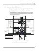
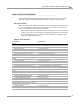
ROOM LAYOUT—MODEL 200IP/250IP DYNO
Use the following information to locate the necessary dyno equipment, power outlets,
compressed air, and properly set up your dyno room.
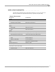
For more detailed information about the pit requirements, refer to the pit
specifications (P/N 98229102) you received from your salesman.
Note: The pit must be provided with exhaust ventilation at a rate of not less than
1CFM per ft.
2
of floor area (26CFM for the 250iP pit) taken from a point 300 mm
(12 in.) off the floor of the pit at all times that the building is occupied or when
vehicles are parked over this area.
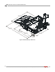
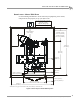
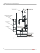
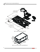
Figure 8: Room Layout—Model 200iP/250iP Top View
Pd186
284.48cm(112.00in.)*
121.92cm
(48.00in.)
60.96cm(24.00in.)
min.dimension
standardcarriage
177.39cm
(69.84in.)
31.09cm
(12.24in.)*
29.84cm(11.75in.)*
60.33cm(23.75in.)*
standardcarriage
320.04cm
(126.00in.)*
standardcarriage
345.44cm
(136.00in.)*
min.dimension
extendedcarriage
220.98cm
(87.00in.)
extendedcarriage
365.76cm
(144.00in.)*
extendedcarriage
436.88cm
(172.00in.)*
*Dimensionsaregivenforreferenceonlyandwillvarywithroomsize.
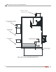
providecompressedairforthe:
•optionalairbrake
•optionalAFR‐4pump
provideanoutletfordynopower