©2009-2013 Dynojet Research, Inc. All Rights Reserved. Linx Installation for Model 424 Automotive Dynamometers This manual is copyrighted by Dynojet Research, Inc., hereafter referred to as Dynojet, and all rights are reserved. This manual, and the software described in it, is furnished under license and may only be used or copied in accordance with the terms of such license.
TABLE OF CONTENTS 424 Linx Installation Introduction . . . . . . . . . . . . . . . . . . . . . . . . . . . . . . . . . . . . . . . . . . . . . . . . . . . 2 Conventions Used In This Manual . . . . . . . . . . . . . . . . . . . . . . . . . . . . . . . . 2 Drill and Drill Bit Requirements . . . . . . . . . . . . . . . . . . . . . . . . . . . . . . . . . . 2 Technical Support . . . . . . . . . . . . . . . . . . . . . . . . . . . . . . . . . . . . . . . . . . . . 2 Linx Belt Drive Specifications . . . . . . . .
TA B L E O F C O N T E N T S Appendix A Red Head Anchor Installation Installation . . . . . . . . . . . . . . . . . . . . . . . . . . . . . . . . . . . . . . . . . . . . . . . . . . .A-2 Appendix B Disconnect the Belt Drive from the Dyno Drums—Early Version Shafts Disconnect the Belt Drive from the Dyno Drums . . . . . . . . . . . . . . . . . . . B-2 Appendix C Shaft Safety Wire Installation Installation . . . . . . . . . . . . . . . . . . . . . . . . . . . . . . . . . . . . . . . . . . . . . . . . . . .
424 LINX INSTALLATION Thank you for your interest in Dynojet’s Automotive Dynamometers. Dynojet’s software and dynamometers will give you the power to get the maximum performance out of vehicles you evaluate. Whether you are new to the benefits of a chassis dynamometer or an experienced performance leader, the repeatability and diagnostic tools of WinPEP 7 software and a Dynojet dynamometer (dyno) will give you the professional results you are looking for.
424 LINX INSTALLATION Introduction INTRODUCTION ................................... Thank you for your interest Dynojet’s Automotive Dynamometers. Before installing the Linx system, please take a moment to read this guide for proper installation procedures. Note: The Linx system is for 88-130-inch wheel base dynos only and cannot be used with the extension kit. CONVENTIONS USED IN THIS MANUAL The conventions used in this manual are designed to protect both the user and the equipment.
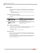
424 LINX INSTALLATION Linx Belt Drive Specifications LINX BELT DRIVE SPECIFICATIONS ................................... The following specifications specific to the Linx belt drive dyno application will help you set up your dyno area and verify you have met the requirements necessary to operate your dyno safely. For more detailed information about your dyno specifications, refer to the installation guide included with your dyno.
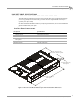
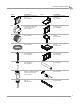
424 LINX INSTALLATION Unpacking the Linx Parts UNPACKING THE LINX PARTS ................................... Use the following steps to unload your Linx system parts. 1 2 part Using a pry bar, or a large flat screwdriver, and a hammer, carefully remove the top and sides of the crate. At this point, you will want to inspect the exterior of the dyno for any indications of damage. Report any damage immediately. Remove the following parts from the crate and set aside.
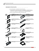
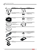
424 LINX INSTALLATION Unpacking the Linx Parts part Version 6 description flange bearing with lock collar (6) P/N 32300001 part description lower stationary pulley mount (3) P/N 61300023 bushing (2) includes three bolts and washers per bushing P/N 32300002 inner stationary dyno mounting plate P/N 61300024 grooved pulley (2) P/N 32300003 upper moveable pulley mount P/N 61300025 safety wire P/N 35300002 lower moveable pulley mount P/N 61300026 screw, 1/4-20 x 1.
424 LINX INSTALLATION Unpacking the Linx Parts part description nut, 9/16-12, hex (24) P/N 36711100 part description nut, 3/8-16, hex (2) P/N DM150-011-004 bolt, 9/16-12 x 2", hex (12) P/N 36811640 bolt, 3/8-16 x 1.
424 LINX INSTALLATION Dynojet Logo Panels and Pit Covers DYNOJET LOGO PANELS AND PIT COVERS ................................... The Linx option can only be installed on one side of the dyno, refer to Figure 1. When the Linx option is being installed on an existing above ground dyno, the Dynojet logo panels must be removed. When the Linx option is being installed on an existing in ground dyno, the pit covers must be removed.
424 LINX INSTALLATION Dynojet Logo Panels and Pit Covers 3 Remove the two 7/16-14 x 1-inch hex bolts, two 7/16-inch flat washers, and two 7/16-14 nuts securing the lower mounting bracket to the dyno. Set the hardware aside. 4 5 Remove the lower mounting bracket and set aside. Remove the two 3/8-16 x 3/4-inch hex bolts and two 3/8-inch flat washers securing each mounting bracket to the dyno. Set the hardware aside. Remove each mounting bracket and set aside.
424 LINX INSTALLATION Dynojet Logo Panels and Pit Covers 7 Remove the two 3/8-16 x 1.5-inch flange hex bolts, washers, and nuts securing the rear deck brace to the mounting bracket. Set the hardware aside. 8 Remove two 3/8-16 x 1.5-inch flange hex bolts securing the rear deck brace mounting bracket to the dyno. Set the hardware aside. Remove the rear deck brace mounting bracket and set aside.
424 LINX INSTALLATION Inner Mounting Plate Installation INNER MOUNTING PLATE INSTALLATION ................................... Use the following instructions to install the moveable dyno and stationary dyno inner mounting plates. You will need the following parts: • • • • • • 36582471 36923100 61300024 61300027 DM150-011-004 DM150-019-012 Bolt, 3/8-16 x 1.
424 LINX INSTALLATION Inner Mounting Plate Installation 2 Using the access holes, secure the bottom of the inner mounting plate to the moveable dyno using two 3/8-16 x 1.5-inch flange bolts, two 3/8-inch flat washers, and two 3/8-inch nuts. access hole XD007 Figure 6: Secure the Bottom of the Inner Mounting Plate to the Moveable Dyno The following steps are for the above ground dyno only.
424 LINX INSTALLATION Inner Mounting Plate Installation INSTALLING THE INNER MOUNTING PLATE—STATIONARY DYNO Secure the inner mounting plate to the stationary dyno using eight 3/8 x 1-inch bolts and eight 3/8-inch flat washers.
424 LINX INSTALLATION Flange Bearing, Outer Shaft, and Splined Shaft Installation FLANGE BEARING, OUTER SHAFT, AND SPLINED SHAFT INSTALLATION ................................... Use the following instructions to install the flange bearing, splined shaft, and outer shaft on both the moveable and stationary dynos. You will need the following parts: 1 2 3 • 32300001 Flange Bearing with Lock Collar (2) • 36500016 Screw, 1/4-20 x 1.
424 LINX INSTALLATION Flange Bearing, Outer Shaft, and Splined Shaft Installation 4 The distance from the face of the bearing mounting plate to the end of the outer shaft should be approximately 16.125-inches. 5 Apply a small amount of grease to the first two inches of the splined shaft. 6 Slide the splined shaft through the outer shaft and into the splines in the dyno drum. Align the two unthreaded holes in the splined shaft flange with the two threaded holes in the outer shaft.
424 LINX INSTALLATION Drive Pulley Installation DRIVE PULLEY INSTALLATION ................................... Use the following instructions to install the drive pulleys for both the moveable and stationary dynos. You will need the following parts: • 32300002 1 Bushing (2) includes three bolts and lock washers each • 32300003 Grooved Pulley (2) Place the bushing into the grooved pulley.
424 LINX INSTALLATION Drive Pulley Installation 4 The outer face of the pulley should be approximately 10-13/16 inches from the face of the inner plate. Slowly tighten the bolts until the hub starts to pull into the pulley, checking that it is approximately 10-13/16 inches from the inner plate before the pulley is locked on the shaft. 5 Tighten the bolts by working around the bushing until none of the bolts will turn at a torque wrench setting of 75 ft.-lb.
424 LINX INSTALLATION Idler Pulley Assembly Installation IDLER PULLEY ASSEMBLY INSTALLATION ................................... You will need the following parts: 1 2 3 4 • 32300001 Flange Bearing with Lock Collar • 36711100 Nut, 9/16-12, Hex (4) • 36943101 Washer, 9/16", Flat (4) • 61100007 Idler Pulley Assembly Place the flange bearing on the threaded studs on the inner plate. Secure the flange bearing to the inner plate using four 9/16-inch flat washers and four 9/16-inch nuts.
424 LINX INSTALLATION Belt and Tensioner Pulley Assembly Installation BELT AND TENSIONER PULLEY ASSEMBLY INSTALLATION ................................... You will need the following parts: • 36923100 Washer, 3/8", Flat (8) • 37513200 Anchor, Red Head, 3/8" (8) • 37518200 Red Head Anchor Installation Tool • 46200006 Belt • 61100008 Tensioner Assembly • DM150-019-012 Bolt, 3/8-16 x 1", Hex (8) Use the following instructions along with Figure 15 on page 19.
424 LINX INSTALLATION Belt and Tensioner Pulley Assembly Installation XD054 tensioner pulley towards stationary dyno apply grease to ACME threads welded nuts towards back Figure 15: Install the Belt and Tensioner Pulley Assembly Version 6 Linx Installation for Model 424 Automotive Dynamometers 19
424 LINX INSTALLATION Pulley Mounting Plates and Outer Bearings Installation PULLEY MOUNTING PLATES AND OUTER BEARINGS INSTALLATION ................................... Note: The inner pulley mounting plates and the pulley mounts are stamped with numbers to help match the parts and guide you in the installation process.
424 LINX INSTALLATION Pulley Mounting Plates and Outer Bearings Installation INSTALLING THE IDLER PULLEY OUTER BEARING, BEARING MOUNTING PLATE, AND LOWER PULLEY MOUNT 1 Secure the outer idler bearing to the idler bearing mounting plate using four 9/16-12 x 2-inch bolts, four 9/16-inch flat washers, and four 9/16-inch nuts. Slide this assembly onto the idler shaft.
424 LINX INSTALLATION Pulley Mounting Plates and Outer Bearings Installation INSTALLING THE MOVEABLE DYNO PULLEY OUTER BEARING, BEARING MOUNTING PLATE, AND LOWER PULLEY MOUNT 1 Secure the outer moveable dyno pulley bearing to the moveable dyno pulley bearing plate using four 9/16-12 x 2-inch bolts, four 9/16-inch flat washers, and four 9/16-inch nuts. Slide this assembly onto the moveable dyno pulley outer shaft.
424 LINX INSTALLATION Pulley Mounting Plates and Outer Bearings Installation INSTALLING THE UPPER MOVEABLE DYNO AND IDLER PULLEY MOUNTS 1 2 Place a lower stationary dyno pulley mount (P/N 61300023) over the moveable dyno pulley and loosely secure the mount to the inner plate using five 3/8-16 x 1-inch bolts and five 3/8-inch flat washers (one of the holes in the pulley mount is not used).
424 LINX INSTALLATION Pulley Mounting Plates and Outer Bearings Installation 3 Place the upper moveable dyno pulley mount (P/N 61300025) over the idler pulley and loosely secure the mount to the inner plate using five 3/8-16 x 1-inch bolts and five 3/8-inch flat washers. 4 Loosely secure the pulley mount to the idler pulley bearing plate using five 3/8-16 x 1-inch bolts and five 3/8-inch flat washers.
424 LINX INSTALLATION Pulley Mounting Plates and Outer Bearings Installation 7 Remove the 1/4-20 x 1.75-inch cap screws from the splined shaft. 8 Verify the splined shaft will slide in and out of the dyno splines easily once all the bolts are tightened. Note: The splined shaft must easily slide in and out of the dyno splines in order to engage and disengage the Linx belt drive. 9 Using the installation instructions included with the bearing, secure the lock collars of both bearings.
424 LINX INSTALLATION Pulley Mounting Plates and Outer Bearings Installation INSTALLING THE STATIONARY DYNO PULLEY OUTER BEARING, BEARING MOUNTING PLATE, AND LOWER PULLEY MOUNT 1 Secure the outer stationary dyno pulley bearing to the stationary dyno pulley bearing plate using four 9/16-12 x 2-inch bolts, four 9/16-inch flat washers, and four 9-16-inch nuts. Slide this assembly onto the stationary dyno pulley outer shaft.
424 LINX INSTALLATION Pulley Mounting Plates and Outer Bearings Installation INSTALLING THE UPPER STATIONARY DYNO PULLEY MOUNT 1 2 3 Place the upper stationary dyno pulley mount (P/N 61300022) over the stationary dyno pulley and loosely secure the mount to the inner plate using five 3/8-16 x 1-inch bolts and five 3/8-inch flat washers (one of the holes on the pulley mount is not used).
424 LINX INSTALLATION Pulley Mounting Plates and Outer Bearings Installation 4 Remove the 1/4-20 x 1.75-inch cap screws from the splined shaft. 5 Verify the splined shaft will slide in and out of the dyno splines easily once all the bolts are tightened. Note: The splined shaft must easily slide in and out of the dyno splines in order to engage and disengage the Linx belt drive. 6 Using the installation instructions included with the bearing, secure the lock collars of the bearing.
424 LINX INSTALLATION Brake Signal Relay Installation BRAKE SIGNAL RELAY INSTALLATION ................................... Use the following instructions along with Figure 27 on page 30 if you are upgrading an existing dyno. If you are installing a new dyno, skip these instructions and continue with “Tension the Belt” on page 31. 1 2 3 4 5 6 7 8 9 10 11 12 13 14 15 16 17 18 Version 6 Disconnect the 4WD power supply. Turn off the power to the dyno electronics.
424 LINX INSTALLATION Brake Signal Relay Installation secure relay to 4WD board using existing nut drum brake from B.O.B.
424 LINX INSTALLATION Tension the Belt TENSION THE BELT ................................... You will need the following part: • 62100003 Tension Arm Assembly Use the following instructions along with Figure 28 on page 32. 1 Verify the drum brakes are released. The dyno wheel base should only be adjusted with the brakes released or the Linx belt drive system disengaged. 2 3 4 5 6 7 Set the dyno to a wheelbase adjustment of 101-inches. Measure 50.5-inches from the center of one of the drums.
424 LINX INSTALLATION Tension the Belt mark 50.50 in.
424 LINX INSTALLATION Above Ground Covers ABOVE GROUND COVERS ................................... You will need the following parts: 1 2 3 4 5 • 21200095 Belt Cover, End Panel (2) • 21200097 Belt Cover, Top (2) • 21400006 Belt Cover, Leg (8) • 21600026 Belt Cover, Center Support • 36561045 Screw, 1/4-20 x 5/8", Pan-Head, Torx (64) • 61100013 Belt Cover, Front Panel Assembly (2) • DM150-020-005 Nut-Crush, 1/4-20 (8) Place the tops flange side up on the floor.
424 LINX INSTALLATION Above Ground Covers 6 Secure the two tops together using two 1/4-20 x 5/8-inch torx screws and two 1/4-20 nuts each. 7 Secure the center support to the tops using four 1/4-20 x 5/8-inch torx screws and four 1/4-20 nuts. Note: When the dyno is equipped with the wheelbase extension kit (P/N 61119183), use the center support (P/N 21200176) included in the kit.
424 LINX INSTALLATION Above Ground Covers 8 Remove the 1/4-20 x 5/8-inch torx screw from the outer most tube of the dyno bridge. 9 Turn the cover assembly over and move towards the dyno. Place the cover so the center support is on the outer tube with the hole lined up as shown. 10 Secure the cover assembly to the dyno using the 1/4-20 x 5/8-inch torx screw removed earlier.
424 LINX INSTALLATION Above Ground Covers 11 Secure each side panel to the cover assembly using seven 1/4-20 x 5/8-inch torx screws.
424 LINX INSTALLATION In Ground Covers IN GROUND COVERS ...................................
4 LINX INSTALLATION In Ground Covers 2 Remove the 1/4-20 x 5/8-inch torx screw from the outer most tube of the dyno bridge. 3 Secure the center support assembly to the outer bridge tube using the screw removed earlier.
424 LINX INSTALLATION In Ground Covers 4 Place the pit cover assemblies on the floor in the position shown. 5 Secure the covers to the center support using two 3/8-16 x 1/2-inch button-head flange bolts.
424 LINX INSTALLATION In Ground Covers 6 Secure the six angle feet to the pit cover assemblies in the positions shown using one 3/8-16 x 1/2-inch button-head flange bolt each. 7 Using the feet as a template, drill each hole needed to secure the feet to the floor. 8 Install the six Red Head anchors. Refer to Appendix A for installation instructions. 9 Secure each foot to the floor using one 3/8-16 x 1-inch hex bolt and one 3/8-inch washer.
424 LINX INSTALLATION Disconnect the Belt Drive from the Dyno Drums DISCONNECT THE BELT DRIVE FROM THE DYNO DRUMS ................................... The Linx belt can be disengaged by pulling the splined shafts out of the dyno splines. 1 Loosen the three finger screws and lower the access panel. For in ground dynos, remove the six 1/4-20 x 5/8-inch torx screws securing each access cover and set aside. Remove each access cover and set aside. 2 3 4 5 Remove the two 1/4-20 x 1.
424 LINX INSTALLATION Disconnect the Belt Drive from the Dyno Drums RECONNECTING THE BELT DRIVE 1 2 3 4 Remove the 1/4-20 x 1.25-inch cap screws from the threaded holes in the splined shaft. Slide the shaft into the dyno drum aligning the two unthreaded holes in the splined shaft flange with the two threaded holes in the outer shaft. Install the 1/4-20 x 1.75-inch cap screws and 1/4-inch lock washers and torque to 7 ft.-lb. (9.5Nm). Secure the cap screws with the shaft safety wire.
APPENDIX A RED HEAD ANCHOR INSTALLATION This appendix contains instructions for installing the Red Head Multi-Set™II Anchors. The anchors will be used to secure the dyno to concrete. To ensure safety and accuracy in the procedures, perform the procedures as they are described. Be sure to read and understand the warnings included in this appendix. WARNINGS Always wear safety glasses and other necessary protective devices or apparel when installing or working with anchors.
APPENDIX A Installation INSTALLATION ................................... Use the table below to determine the catalog number, drill bit size, minimum hole depth, and setting tool catalog number. catalog number Carbon Steel RM-38/RL-38 (9.5 mm) drill bit size 1/2-inch minimum hole depth 1 5/8-inch (41.2 mm) setting tool catalog number RT-138 Use the following instructions to install the Red Head anchors.
RED HEAD ANCHOR INSTALLATION Installation 3 Using a hammer, drive the anchor flush with the surface of the concrete, or below the surface if the hole depth exceeds minimum embedment. Figure A-3: Red Head Anchor—Drive the Anchor Flush 4 Using a hammer, expand the anchor with the setting tool. The anchor is properly expanded when the shoulder of the setting tool is flush with the top of the anchor. Note: Use only Ramset/Red Head setting tools to insure proper installtion.
APPENDIX B DISCONNECT THE BELT DRIVE FROM THE DYNO DRUMS—EARLY VERSION SHAFTS This appendix contains instructions for disconnecting the belt drive from the dyno drums using early version shafts.
APPENDIX B Disconnect the Belt Drive from the Dyno Drums DISCONNECT THE BELT DRIVE FROM THE DYNO DRUMS ................................... The Linx belt can be disengaged by pulling the splined shafts out of the dyno splines. You will need the following part: 1 2 • 62100002 Shaft Puller Assembly Remove the nine 1/4-20 x 5/8-inch torx screws securing each side panel and set aside. Remove the side panels and set aside.
D I S C O N N E C T T H E B E L T D R I V E F R O M T H E D Y N O D R U M S — E A R L Y VE R S I O N S H A F T S Disconnect the Belt Drive from the Dyno Drums 6 If you are unable to pull the shaft out by hand, remove the top access cover and use the shaft puller as shown.
APPENDIX C SHAFT SAFETY WIRE INSTALLATION This appendix contains instructions for installing the shaft safety wire. To ensure safety and accuracy in the procedures, perform the procedures as they are described.
APPENDIX C Installation INSTALLATION ................................... Use the following instructions to install the shaft safety wire. Failure to secure the cap screws with safety wire can result in damage to the dyno and/or the vehicle. 1 2 3 4 Torque the cap screws to 7 ft.-lb. (9.5Nm). Bend the wire into a U shape with equal ends. Insert the wire through the hole in the bolt. Loop one end of the wire around the bolt clock-wise and match up the ends of the wire.