
Installation Guide User Manual

424 LINX INSTALLATION
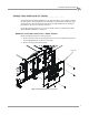
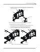
Inner Mounting Plate Installation
Version 6 Linx Installation for Model 424 Automotive Dynamometers
11
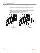
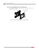
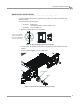
2 Using the access holes, secure the bottom of the inner mounting plate to the
moveable dyno using two 3/8-16 x 1.5-inch flange bolts, two 3/8-inch flat washers,
and two 3/8-inch nuts.
Figure 6: Secure the Bottom of the Inner Mounting Plate to the Moveable Dyno
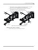
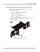
The following steps are for the above ground dyno only.
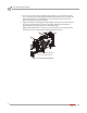
3 Secure the rear deck brace mounting bracket to the inner mounting plate and
dyno using the two 3/8-16 x 1.5-inch flange-hex bolts removed earlier.
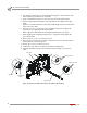
4 Secure the rear deck brace to the mounting bracket using the two
3/8-16 x 1.5-inch flange-hex bolts, washers, and nuts removed earlier.
Figure 7: Secure the Rear Deck Brace and Mounting Bracket
XD007
access hole
XD008
XD009
rear deck brace
mounting bracket
rear deck brace