
Installation Guide User Manual

424 LINX INSTALLATION
Drive Pulley Installation
Version 6 Linx Installation for Model 424 Automotive Dynamometers
15
. . . . . . . . . . . . . . . . . . . . . . . . . . . . . . . . . . .
DRIVE PULLEY INSTALLATION
Use the following instructions to install the drive pulleys for both the moveable and
stationary dynos.
You will need the following parts:
• 32300002 Bushing (2)
includes three bolts and lock washers each
• 32300003 Grooved Pulley (2)
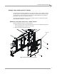
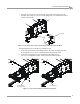
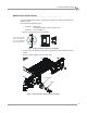
1 Place the bushing into the grooved pulley.
Figure 11: Align the Bushing in the Grooved Pulley
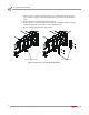
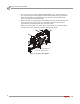
2 Loosely secure the bushing in the pulley using the three included bolts and lock
washers.
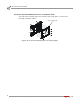
3 Slide the pulley assembly onto the outer shaft.
Figure 12: Install the Moveable Dyno Pulley Assembly
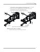
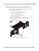
grooved pulley
bushing
section view of bushing
and grooved pulley to
show correct alignment
with the tapered hole
XD051
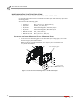
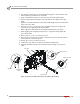
bushing
grooved pulley