
Installation Guide User Manual

424 LINX INSTALLATION
Idler Pulley Assembly Installation
Version 6 Linx Installation for Model 424 Automotive Dynamometers
17
. . . . . . . . . . . . . . . . . . . . . . . . . . . . . . . . . . .
IDLER PULLEY ASSEMBLY INSTALLATION
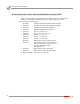
You will need the following parts:
• 32300001 Flange Bearing with Lock Collar
• 36711100 Nut, 9/16-12, Hex (4)
• 36943101 Washer, 9/16", Flat (4)
• 61100007 Idler Pulley Assembly
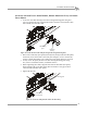
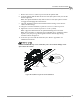
1 Place the flange bearing on the threaded studs on the inner plate.
2 Secure the flange bearing to the inner plate using four 9/16-inch flat washers and
four 9/16-inch nuts.
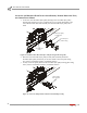
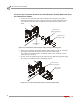
3 Holding the idler assembly horizontal, slide the assembly into the bearing until its
outer edge is approximately 11-1/8-inches from the face of the inner plate.
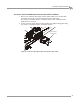
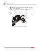
4 Using the installation instructions included with the bearing, secure the lock
collar.
Note: Refer to the installation instructions included with the bearing.
Carefully allow the idler pulley assembly to hang in the bearing.
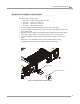
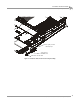
Figure 14: Install the Idler Pulley Assembly
XD053
flange bearing
idler pulley assembly