
Installation Guide User Manual


Linx Installation for Model 424 Automotive Dynamometers
424 LINX INSTALLATION
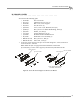
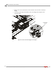
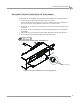
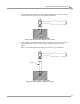
Disconnect the Belt Drive from the Dyno Drums
42
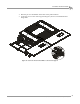
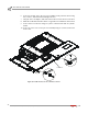
RECONNECTING THE BELT DRIVE
1 Remove the 1/4-20 x 1.25-inch cap screws from the threaded holes in the splined
shaft.
2 Slide the shaft into the dyno drum aligning the two unthreaded holes in the
splined shaft flange with the two threaded holes in the outer shaft.
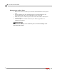
3 Install the 1/4-20 x 1.75-inch cap screws and 1/4-inch lock washers and torque to
7 ft.-lb. (9.5Nm).
4 Secure the cap screws with the shaft safety wire. Refer to Appendix C for
installation instructions.
Failure to secure the cap screws with safety wire can result in damage to the
dyno and/or the vehicle