
Installation Guide User Manual

Linx Installation for Model 424 Automotive Dynamometers
1
424 L
INX
I
NSTALLATION
Thank you for your interest in Dynojet’s Automotive Dynamometers. Dynojet’s
software and dynamometers will give you the power to get the maximum
performance out of vehicles you evaluate. Whether you are new to the benefits of a
chassis dynamometer or an experienced performance leader, the repeatability and
diagnostic tools of WinPEP 7 software and a Dynojet dynamometer (dyno) will give
you the professional results you are looking for.
The Linx belt drive system synchronizes the speed of the front and rear drums for
testing sensitive all-wheel drive and two-wheel drive vehicles with traction control.
This document is designed to help you install the Linx system on your model 424
automotive dyno. To ensure safety and accuracy in the procedures, perform the
procedures as they are described.
Note: The Linx system is for 88-130-inch wheel base dynos only and cannot be
used with the extension kit.
Document Part Number: 98200021
Version 6
Last Updated: 05-30-13
This chapter is divided into the following categories:
•Introduction, page 2
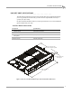
• Linx Belt Drive Specifications, page 3
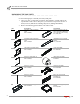
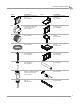
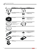
• Unpacking the Linx Parts, page 4
• Dynojet Logo Panels and Pit Covers, page 7
• Inner Mounting Plate Installation, page 10
• Flange Bearing, Outer Shaft, and Splined Shaft Installation, page 13
• Drive Pulley Installation, page 15
• Idler Pulley Assembly Installation, page 17
• Belt and Tensioner Pulley Assembly Installation, page 18
• Pulley Mounting Plates and Outer Bearings Installation, page 20
• Brake Signal Relay Installation, page 29
• Tension the Belt, page 31
• Above Ground Covers, page 33
• In Ground Covers, page 37
• Disconnect the Belt Drive from the Dyno Drums, page 41