
Installation Guide User Manual


Linx Installation for Model 424 Automotive Dynamometers
APPENDIX B
Disconnect the Belt Drive from the Dyno Drums
B-2
. . . . . . . . . . . . . . . . . . . . . . . . . . . . . . . . . . .
DISCONNECT THE BELT DRIVE FROM THE DYNO DRUMS
The Linx belt can be disengaged by pulling the splined shafts out of the dyno splines.
You will need the following part:
• 62100002 Shaft Puller Assembly
1 Remove the nine 1/4-20 x 5/8-inch torx screws securing each side panel and set
aside.
2 Remove the side panels and set aside.
For in ground dynos, remove the six 1/4-20 x 5/8-inch torx screws securing each
access cover and set aside. Remove each access cover and set aside.
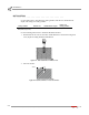
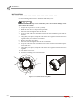
3 Remove the cotter keys and clevis pins.
4 Insert a 3/8-inch bolt into the end of the splined shaft about three turns.
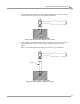
5 At each drum, pull the splined shaft out at least four inches.
Always disengage the belt drive at BOTH dynos.
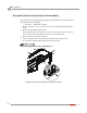
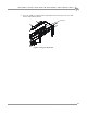
Figure B-1: Disconnect the Belt Drive from the Dyno Drums
XD038