
Installation Guide Instruction Manual
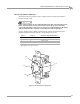


In Ground Model 424x/424xLC
2
Automotive Dynamometer Installation Guide
APPENDIX B
Power Requirements and Installation—Excluding North America and Japan
B-6
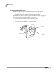
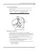
INSTALLING THE WALL RECEPTACLE
The wall receptacle is a single 240 volt 30A dedicated circuit with a ground.
Note: The actual wall receptacle may be different from the image shown in
Figure B-2; however, the installation instructions are the same.
The cable carrying the power to this receptacle should be 4.0 mm
2
(ten gauge) or
larger. Check with local building codes for the correct size.
1 Connect one of the 240V legs to the N terminal (no color).
2 Connect the other 240V leg to the L terminal (no color).
3 Connect the ground conductor to the green terminal.
Figure B-2: Wiring the Wall Receptacle
N terminal
L terminal
ground terminal
(green)