
Installation Guide Instruction Manual
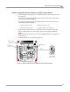
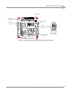

4WD DYNO INSTALLATION
Cable Routing
Version 7 In Ground Model 424x/424xLC
2
Automotive Dynamometer Installation Guide
3-15
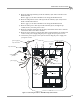
WIRING THE BREAKOUT BOARD—WITHOUT THE EDDY CURRENT BRAKES
1 Attach the pickup card cable (B, C) to the Breakout board. This cable may already
be connected.
The pickup card cable (B) from the stationary dyno has four wires which connect
to the wiring block labeled DRUM 1.
The pickup card cable (C) from the 4WD dyno has four wires which connect to
the wiring block labeled DRUM 2.
2 Attach the brake signal cable (D) to the Breakout board. The brake signal cable
from the 4WD dyno has two wires which connect to the wiring block labeled
BRAKE.
Note: There will already be wires connected to BRAKE; add the brake signal wires
to this location.
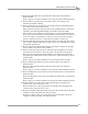
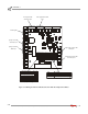
3 Verify the jumpers are set as shown in Figure 3-9.
Figure 3-9: Wiring the Breakout Board—Without the Eddy Current Brakes
• Red wire connects to R1 • Black wire connects to B1
• White wire connects to W1 • Ground (shield) wire connects to S1
jumpers
J1 and J2
four wheel drive
with no eddy
current brake
jumper settings
pickup card
stationary
pickup card
4WD
brake signal
J1
J2