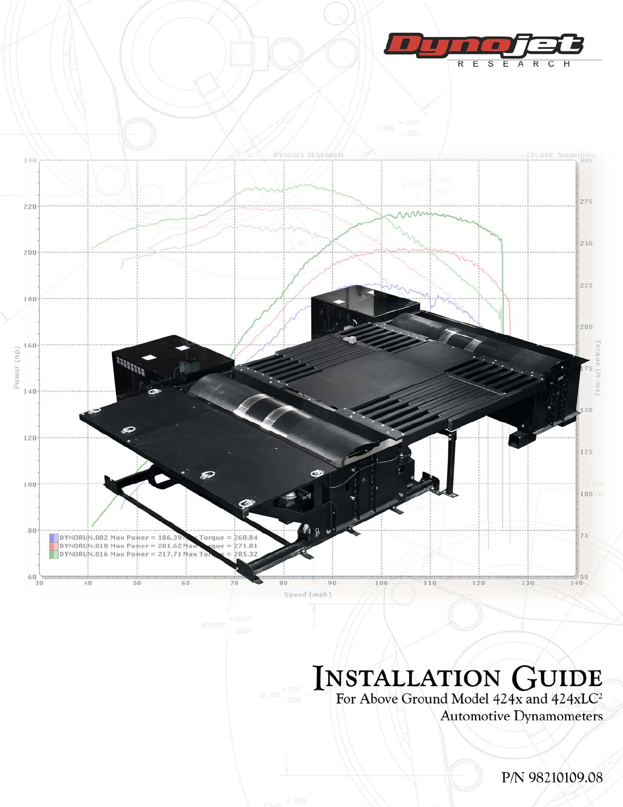
©2006-2013 Dynojet Research, Inc. All Rights Reserved. Installation Guide For Above Ground Model 424x and 424xLC2 Automotive Dynamometers. This manual is copyrighted by Dynojet Research, Inc., hereafter referred to as Dynojet, and all rights are reserved. This manual, and the software described in it, is furnished under license and may only be used or copied in accordance with the terms of such license.
TABLE OF CONTENTS Warnings Chapter 1 ................................................ v Specifications and Operating Requirements Introduction . . . . . . . . . . . . . . . . . . . . . . . . . . . . . . . . . . . . . . . . . . . . . . . . . . 1-2 Conventions Used In This Manual . . . . . . . . . . . . . . . . . . . . . . . . . . . . . . . 1-3 Technical Support . . . . . . . . . . . . . . . . . . . . . . . . . . . . . . . . . . . . . . . . . . . 1-3 Dynamometer Specifications and Requirements . . . . . . .
TA B L E O F C O N T E N T S Chapter 3 4WD Dyno Installation Unpacking and Inspecting the Dyno . . . . . . . . . . . . . . . . . . . . . . . . . . . . . . 3-2 Track Assembly . . . . . . . . . . . . . . . . . . . . . . . . . . . . . . . . . . . . . . . . . . . . . . . 3-4 Installing the Track Assembly . . . . . . . . . . . . . . . . . . . . . . . . . . . . . . . . . . . 3-6 Dyno Installation . . . . . . . . . . . . . . . . . . . . . . . . . . . . . . . . . . . . . . . . . . . . . .
TA B L E O F C O N T E N T S Chapter 4 Eddy Current Brake Installation Eddy Current Brake Installation . . . . . . . . . . . . . . . . . . . . . . . . . . . . . . . . . . 4-2 Before Installing the Eddy Current Brake: Verify Optimal Brake Cooling . . . 4-2 Before Installing the Eddy Current Brake: Verify Mounting Holes . . . . . . . . 4-3 Unpacking the Eddy Current Brake . . . . . . . . . . . . . . . . . . . . . . . . . . . . . . 4-4 Installing the Temperature Sensor . . . . . . . . . . . . . . . . . . . .
TA B L E O F C O N T E N T S Appendix B Power Requirements and Installation Power Requirements and Installation—North America, Japan, and Locations Using 60 Hz Power . . . . . . . . . . . . . . . . . . . . . . . . . . . . . . . . B-2 Installing the Wall Receptacle . . . . . . . . . . . . . . . . . . . . . . . . . . . . . . . . . . . B-2 Testing for Correct Voltages . . . . . . . . . . . . . . . . . . . . . . . . . . . . . . . . . . . . B-3 Hard Wiring to the Building . . . . . . . . . . . . . . . . . . . .
WARNINGS Disclaimers Dynojet Research, Inc. (Dynojet) makes no representation or warranties with respect to the contents hereof and specifically disclaims any implied warranties of merchantability for any particular purpose. Dynojet reserves the right to revise this publication and to make changes from time to time in the content hereof without obligation of Dynojet to notify any person of such revision or changes.
WA R N I N G S Electrostatic Discharge Precautions Electrostatic Discharge Electrostatic Discharge (ESD), or static shock, can damage electronic components within the dynamometer. The damage may occur at the time of an ESD occurrence, or the shock may degrade the component, resulting in a premature component failure later. To avoid ESD damage, always practice good ESD control precautions when servicing the dynamometer.
WA R N I N G S Other Potential Hazards The AC power outlet shall be installed near the equipment and it shall be easily accessible to allow for disconnect before service. The dynamometer should be located in a well ventilated area. There is a carbon monoxide hazard with all internal combustion engines. Engine exhaust contains poisonous carbon monoxide gas. Breathing it could cause death. Any dyno room design must incorporate sufficient exhaust extraction. Equipment is intended for indoor use only.
CHAPTER 1 SPECIFICATIONS AND OPERATING REQUIREMENTS Thank you for purchasing Dynojet’s Above Ground Model 424x/424xLC2 Automotive Dynamometer (dyno). Dynojet’s software and dynamometers will give you the power to get the maximum performance out of the vehicles you evaluate.
CHAPTER 1 Introduction INTRODUCTION ................................... Before installing your dyno, please take a moment to read this guide for installation instructions, dyno features, and other important information. This guide is designed to be a reference tool in your everyday work and includes the following chapters and information: SPECIFICATIONS AND OPERATING REQUIREMENTS This chapter describes the specifications and requirements for the dyno.
SPECIFICATIONS AND OPERATING REQUIREMENTS Introduction CONVENTIONS USED IN THIS MANUAL The conventions used in this manual are designed to protect both the user and the equipment. example of convention RECORD # Bold description The Caution icon indicates a potential hazard to the dynamometer equipment. Follow all procedures exactly as they are described and use care when performing all procedures.
CHAPTER 1 Dynamometer Specifications and Requirements DYNAMOMETER SPECIFICATIONS AND REQUIREMENTS ................................... The following specifications and requirements will help you set up your dyno area and verify you have the requirements necessary to operate your dyno safely.
SPECIFICATIONS AND OPERATING REQUIREMENTS Dynamometer Specifications and Requirements 115.49 cm (45.47 in.) frame, air brake, and interface kit 93.83 cm (36.94 in.) frame and air brake 106.93 cm (42.10 in.) brake 73.66 cm (29.00 in.) 72.02 cm (28.375 in.) frame to floor AD279 58.42 cm (23.00 in.) frame only 218.44 cm (86.00 in.) 321.23 cm (126.47 in.) frame and brake 65.58 cm (25.82 in.) brake only 80.01 cm (31.50 in.
CHAPTER 1 Dynamometer Specifications and Requirements 193.45 cm (76.16 in.) frame, cradle assembly, and deck 130.18 cm (51.25 in.) frame and cradle assembly 73.66 cm (29.00 in.) frame 218.44 cm (86.00 in.) frame only 321.23 cm (126.47 in.) frame and brake AD506 218.44 cm (86.00 in.) track 228.60 cm (90.00 in.) deck 224.15 cm (88.25 in.) track 65.58 cm (25.82 in.) brake only 80.01 cm (31.50 in.
SPECIFICATIONS AND OPERATING REQUIREMENTS Dynamometer Specifications and Requirements extension kit dimensions* 533.40 cm (210.00 in.) deck full out to lift 441.96 cm (174.00 in.) deck full in to lift 508.00 cm (200.00 in.) deck full out to lift 416.56 cm (164.00 in.) deck full in to lift 513.08 cm (202.00 in.) frame and deck full out 422.40 cm (166.30 in.) frame and deck full in 487.68 cm (192.00 in.) frame and deck full out 397.00 cm (156.30 in.) frame and deck full in 91.44 cm (36.00 in.) 229.
CHAPTER 1 Dynamometer Specifications and Requirements COMPRESSED AIR The following requirements are needed for the air brake: • Clean and dry air, between 100-140 psi • shut off valve • 1/4-inch NPT pipe thread connector (to attach air to the dyno), if air hose does not have a 3/8-inch inside diameter • have a 3/8-inch inside diameter COMPUTER SPECIFICATIONS You will need to provide a computer system to run the WinPEP software.
SPECIFICATIONS AND OPERATING REQUIREMENTS Dynamometer Specifications and Requirements FIRE SUPPRESSION Always have adequate fire suppression or fire extinguishers in your dyno room. FORKLIFT REQUIREMENTS You will need to provide equipment capable of lifting 2,495 kg (5,500 lb.) to lift the crated dyno and to lift the dyno off the crate and into position in your dyno room. You will also need a pair of straps capable of supporting the uncrated dyno. Dynojet recommends using single loop style straps.
CHAPTER 1 Model 424 Stationary and 4WD Dynamometer MODEL 424 STATIONARY AND 4WD DYNAMOMETER ...................................
SPECIFICATIONS AND OPERATING REQUIREMENTS Model 424 4WD Dynamometer With Bridge and Deck MODEL 424 4WD DYNAMOMETER WITH BRIDGE AND DECK ...................................
CHAPTER 1 Dyno Electronics DYNO ELECTRONICS ................................... The standard dyno electronics package is comprised of four interconnected modules. Use the figure below to identify the modules and connectors when routing cables. A detailed description of each module along with the instructions for connecting the dyno electronics to the WinPEP 7 software can be found in your WinPEP 7 User Guide.
SPECIFICATIONS AND OPERATING REQUIREMENTS Lift Specifications and Requirements LIFT SPECIFICATIONS AND REQUIREMENTS ................................... Dynojet recommends installing the four-post lift before installing your dynamometer. However, if space constraints make it difficult to install the lift first, the dynamometer can be installed before the lift. Dynojet acts as a liaison for Rotary Lifts, to ensure that you receive the proper four-post lift.
CHAPTER 2 STATIONARY DYNO INSTALLATION This chapter will walk you through unpacking and installing the stationary dyno. To ensure safety and accuracy in the procedures, perform the procedures as they are described.
CHAPTER 2 Unpacking and Inspecting the Dyno UNPACKING AND INSPECTING THE DYNO ................................... When you receive your dyno, examine the exterior of the shipping container for any visible damage. If damage is detected at this stage, contact the shipper or Dynojet before proceeding with unpacking. Use the following steps to unload your dyno. You will need to provide equipment capable of lifting a minimum of 2,114 kg (4,660 lb.) to move the crated dyno into position in your dyno room.
STATIONARY DYNO INSTALLATION Unpacking and Inspecting the Dyno part Version 8 description runner tie slide (2) P/N 21214705 part description runner support pillar assembly (4) P/N 61314500 side deck P/N 21216101 riser foot assembly (4) P/N 61319600 side deck, left P/N 21216102 dyno electronics P/N 76199001 side deck, center P/N 21216103 bolt kit, 424 bridge P/N 79110002 runner mount, short (2) P/N 21514801 bolt kit, 4WD above ground P/N 79110004 runner mount (2) P/N 21514802 bolt kit, 3/8-16
CHAPTER 2 Unpacking and Inspecting the Dyno part description bolt, 3/8-16 x 1.
STATIONARY DYNO INSTALLATION Unpacking and Inspecting the Dyno part description outer panel, deck (2) P/N 21214301 part description bolt, 7/16-14 x 1", hex (4) P/N 36591670 right drum guard P/N 21216101 washer, 7/16", flat (4) P/N 36933100 left drum guard P/N 21216102 logo panel assembly (2) P/N 61100001 lateral drum guard (2) P/N 21216103 interface guide assembly P/N 71300000 support angel, deck (2) P/N 21610807 bolt kit, 224-2 above ground P/N 79110003 brace mount, deck (2) P/N 21614102 wash
CHAPTER 2 Unpacking and Inspecting the Dyno part description part The following parts are included in the Retarder Upgrade P/N 77010003: splined shaft P/N 22117130 driveline assembly P/N 62240130 bearing, flange P/N 32355056 torque module P/N 66104001 screw, 8-32 x 3/8", pan-head, sems, phil (4) P/N 36540647 theta controller P/N 66411004 nut, 1/2-13, nylock, hex (4) P/N 36708100 load cell assembly P/N 76950505 bolt, 1/2-13 x 1.
STATIONARY DYNO INSTALLATION Dyno Installation DYNO INSTALLATION ................................... This section will walk you through removing the dyno from the crate and installing the dyno in front of your lift. Refer to Appendix C for instructions on upgrading an existing dyno. REMOVING THE DYNO FROM THE CRATE You will need to provide equipment capable of lifting a minimum of 2,114 kg (4,660 lb.) to lift the dyno off the crate and into position in your dyno room.
CHAPTER 2 Dyno Installation 8 With the dyno on the forklift, secure the four feet to the bottom of the dyno using the four 3/8 x 1.5-inch flange bolts removed earlier. Note: If the feet are already installed, skip this step.
STATIONARY DYNO INSTALLATION Dyno Installation PLACING THE DYNO IN FRONT OF THE LIFT 1 2 3 4 5 Verify the interface bracket faces the lift as shown in Figure 2-3. Verify the lift is in the down position. Using the forklift, bring the dyno in front of the lift. The dyno should be about 10.16 cm (4.00 in.) from the lift cross member. Center the dyno drum with the lift runways. Gently lower the dyno into position. lift runway lift runway interface bracket 10.16 cm (4.00 in.
CHAPTER 2 Dyno Installation INSTALLING THE INTERFACE GUIDE The interface guide secures the dyno to the four-post lift. It is a good idea to install your interface guide before anchoring your dyno to the ground. If you have the interface roller assembly, refer to Appendix E. You will need the following parts: • 21600000 • 21600001 1 2 Interface Bar Interface Bracket secured to the dyno using P/N 36582471 Bolt, 3/8-16 x 1.5", Flange-Hex (2) • 36488100 Nut, 3/8-16, Nylock (2) • 36500000 Bolt, 3/8-16 x 4.
STATIONARY DYNO INSTALLATION Dyno Installation 3 Align the interface guide pin on the lift cross member with the interface bracket on the dyno. The interface bracket is already installed on the dyno. Note: The distance between the dyno and the lift may need to be adjusted. 4 Lower the lift until the interface guide pin just starts to enter the interface bracket on the dyno.
CHAPTER 2 Dyno Installation 5 6 7 8 9 Verify the interface guide clears the interface bracket by 1/8-inch to 1/4-inch as shown in Figure 2-6. Slide the interface guide up until the bottom bolt touches the cross member. Lower the top bolt down in the slots until it touches the cross member. Tighten the hardware securing the interface guide to the lift cross member. Note: The lower and upper interface guide mounting bolts should touch the lift cross member.
STATIONARY DYNO INSTALLATION Dyno Installation ANCHORING THE DYNO Dynojet recommends you secure your dyno to the floor in your dyno room using concrete anchors. Use the following instructions to secure the dyno to the floor.
CHAPTER 3 4WD DYNO INSTALLATION This chapter will walk you through unpacking and installing the 4WD dyno. To ensure safety and accuracy in the procedures, perform the procedures as they are described.
CHAPTER 3 Unpacking and Inspecting the Dyno UNPACKING AND INSPECTING THE DYNO ................................... When you receive your dyno, examine the exterior of the shipping container for any visible damage. If damage is detected at this stage, contact the shipper or Dynojet before proceeding with unpacking. Use the following steps to unload your dyno. You will need to provide equipment capable of lifting a minimum of 2,495 kg (5,500 lb.) to move the crated dyno into position in your dyno room.
4WD DYNO INSTALLATION Unpacking and Inspecting the Dyno part description spacer, rail clamp (8) P/N 26152020 description rail clamp (4) P/N 61314700 rail clip (10) P/N 31619500 calibration arm assembly P/N 61319001 clevis pin, 3/4 x 4.5" (2) P/N 32900000 runner assembly (30) P/N 61319500 hairpin cotter, 7/16 x 3/4" (2) P/N 32904080 washer, 1/4", flat (4) P/N DM150-009-003 weight (4) P/N 35430899 washer, 3/8", flat (4) P/N DM150-011-002 bolt, 3/8-16 x 1.
CHAPTER 3 Track Assembly TRACK ASSEMBLY ................................... The stationary dyno must be installed before proceeding with the 4WD dyno installation. Refer to chapter 2 for stationary dyno installation instructions. Before installing the track assembly, layout the entire track assembly using the following instructions and Figure 3-1 for position and alignment.
4WD DYNO INSTALLATION Track Assembly stationary dyno 128.27 cm (50.50 in.) without extension 153.67 cm (60.50 in.) with extension (requires extension parts, inquire with Dynojet sales) center line for stationary dyno and track assembly 184.15 cm (72.5 in.) track layout first rail tie assembly 49.37 cm (19.438 in.) first rail tie mark and drill holes 103.82 cm (40.875 in.) second rail tie 158.28 cm (62.313 in.
CHAPTER 3 Track Assembly INSTALLING THE TRACK ASSEMBLY Once all the holes are marked and drilled, install the track assembly. You will need the following parts: 1 2 3 • 21514282 Rail (2) • 21716400 Rail Tie (3) • 31619500 Rail Clip (10) • 36582471 Bolt, 3/8-16 x 1.5", Flange-Hex (10) • 61314300 Rail Tie Assembly (2) • 61314700 Rail Clamp (4) Layout the first and last rail tie assemblies and the rail ties. Use the holes you marked and drilled for placement of the rail tie assemblies and rail ties.
4WD DYNO INSTALLATION Track Assembly 4 5 6 Loosely install the ten rail tie clips using one 3/8-16 x 1.5-inch flange-hex bolt per clip. There are five rail tie clips on each side of the track assembly. Verify the track assembly is square and make any necessary adjustments. Tighten all ten bolts. Note: For clarity, the stationary dyno is not shown.
CHAPTER 3 Dyno Installation DYNO INSTALLATION ................................... With the track assembly installed and secured to the floor, you are ready to install the 4WD dyno. This section will walk you through removing the dyno from the crate and securing the dyno to the track. REMOVING THE DYNO FROM THE CRATE You will need to provide equipment capable of lifting a minimum of 2,495 kg (5,500 lb.) to lift the dyno off the crate and into position in your dyno room.
4WD DYNO INSTALLATION Dyno Installation PLACING THE DYNO ON THE TRACK You will need to keep the cable track routed underneath the dyno and towards the stationary dyno. You will need the following parts: 1 2 3 4 • 26152020 Spacer, Rail Clamp (8) • 36800973 Bolt, Shoulder, 3/8-16, 1/2"D x 1"L (8) Remove the cotter pin and pin from all four cradle assemblies as shown in Figure 3-5. Verify the rail clamps are positioned as shown in Figure 3-5.
CHAPTER 3 Dyno Installation 5 6 7 8 Secure the rail clamps to the cradle assembly on the dyno using two 3/8-inch shoulder bolts and two spacers each. Replace the pins and cotter pins removed earlier from the four cradle assemblies as shown in Figure 3-5. Move the rail clamps up and down and verify they move freely. Roll the dyno back and forth and verify the rail clamps are not binding and the track assembly is square. Note: For clarity, the stationary dyno is not shown.
4WD DYNO INSTALLATION Cable Routing CABLE ROUTING ................................... Use the following instructions to identify and route the cables for dynos with and without eddy current brakes.
CHAPTER 3 Cable Routing ROUTING THE CABLES—WITHOUT THE EDDY CURRENT BRAKES Use these instructions for routing cables without the eddy current brake. Refer to page 3-15 for more information on routing cables with one eddy current brake and page 3-19 for more information on routing cables with two eddy current brakes. Refer to Figure 3-7 for cable locations. Refer to page 3-14 for more information on wiring the Breakout board.
4WD DYNO INSTALLATION Cable Routing power supply for dyno electronics Breakout board DRY AIR IN 100-140 PSI AD371 B stationary dyno A D dyno electronics H C E G power supply F dyno movement pendant I first cable track second cable track 4WD dyno Figure 3-7: Routing the Cables—Without the Eddy Current Brakes Version 8 Above Ground Model 424x/424xLC2 Automotive Dynamometer Installation Guide 3-13
CHAPTER 3 Cable Routing WIRING THE BREAKOUT BOARD—WITHOUT THE EDDY CURRENT BRAKES 1 Attach the pickup card cable (B, C) to the Breakout board. This cable may already be connected. The pickup card cable (B) from the stationary dyno has four wires which connect to the wiring block labeled DRUM 1. The pickup card cable (C) from the 4WD dyno has four wires which connect to the wiring block labeled DRUM 2.
4WD DYNO INSTALLATION Cable Routing ROUTING THE CABLES—WITH ONE EDDY CURRENT BRAKE Use these instructions for routing cables with only one eddy current brake. The single eddy current brake is installed on the stationary dyno. Refer to Chapter 4 for eddy current brake, torque module, and load cell installation instructions. Refer to page 3-19 for more information on routing cables with two eddy current brakes. Refer to Figure 3-9 for cable locations.
CHAPTER 3 Cable Routing 12 Route the temperature sensor cable (N) from the stationary dyno to the Breakout board. Refer to page 3-14 for more information on wiring the Breakout board. 13 Route the theta power cable (P) from the stationary dyno to your 240V power source. 14 Route the controller cable (R) from the stationary eddy current brake to the theta controller. Connect the cable to the theta controller. 15 Route the power cable (G) from the first cable track and connect to the power supply.
4WD DYNO INSTALLATION Cable Routing WIRING THE BREAKOUT BOARD—WITH ONE EDDY CURRENT BRAKE 1 Attach the pickup card cable (B, C) to the Breakout board. This cable may already be connected. The pickup card cable (B) from the stationary dyno has four wires which connect to the wiring block labeled DRUM 1. The pickup card cable (C) from the 4WD dyno has four wires which connect to the wiring block labeled DRUM 2.
CHAPTER 3 Cable Routing theta signal pickup card stationary brake signal pickup card 4WD jumpers J1 and J2 temperature sensor four wheel drive with one eddy current brake jumper settings Figure 3-10: Wiring the Breakout Board—With One Eddy Current Brake 3-18 Above Ground Model 424x/424xLC2 Automotive Dynamometer Installation Guide
4WD DYNO INSTALLATION Cable Routing ROUTING THE CABLES—WITH TWO EDDY CURRENT BRAKES Use these instructions for routing cables with two eddy current brakes. Refer to Chapter 4 for eddy current brake, torque module, and load cell installation instructions. Refer to Figure 3-12 for cable locations. Refer to page 3-22 for more information on wiring the Advanced Breakout board.
CHAPTER 3 Cable Routing 11 Route the air hose (E) from the second cable track to the T fitting on the stationary dyno brake solenoid. 12 Route the long air hose (F) from the second cable track to the barbed fitting on the air brake can on the stationary dyno. Note: Verify the stationary dyno has clean dry air regulated between 100-140 psi supplied to the remaining barbed fitting on the brake solenoid assembly. The air brake comes installed with a hose barb for a 3/8-inch inside diameter air hose.
4WD DYNO INSTALLATION Cable Routing 21 Route the power cable (G) from the first cable track and connect to the power supply. Plug the power supply into your power source. 22 Connect the power supply to the dyno electronics. Plug the power supply into your power source.
CHAPTER 3 Cable Routing WIRING THE ADVANCED BREAKOUT BOARD—WITH TWO EDDY CURRENT BRAKES Refer to Figure 3-13 for Advanced Breakout board locations. 1 Attach the pickup card cable (B, C) to the Advanced Breakout board. The pickup card cable (B) from the stationary dyno has four wires which connect to the wiring block labeled DRUM 1. The pickup card cable (C) from the 4WD dyno has four wires which connect to the wiring block labeled DRUM 2.
4WD DYNO INSTALLATION Cable Routing .
CHAPTER 3 Hydraulic Movement Installation HYDRAULIC MOVEMENT INSTALLATION ................................... Use the following instructions to install the hydraulic movement. You will need the following parts: 1 • 26100000 Spacer,424 Hydraulic Movement (2) • 32900000 Clevis Pin, 3/4 x 4.5" (2) • 32904080 Hairpin Cotter, 7/16 x 3/4" (2) • 36582471 Bolt, 3/8-16 x 1.
4WD DYNO INSTALLATION Hydraulic Movement Installation 2 Secure the hydraulic ram to the dyno cylinder mount using one clevis pin and hairpin cotter.
CHAPTER 3 Hydraulic Movement Installation 3 Temporarily hold the floor cylinder mount to the hydraulic ram using two spacers and one clevis pin.
4WD DYNO INSTALLATION Hydraulic Movement Installation 4 5 6 7 8 9 Using the floor cylinder mount as a template, mark each hole needed to secure the mount to the floor. Remove the clevis pin, spacers, and floor cylinder mount. Move the hydraulic ram out of the way. Drill the holes marked in step #4. Install the Red Head anchors. Refer to Appendix A for installation instructions. Secure the floor cylinder mount to the floor using four 3/8-16 x 1-inch hex bolts and four 3/8-inch flat washers.
CHAPTER 3 Hydraulic Movement Installation ROTATING THE HYDRAULIC MOTOR Before rotating the hydraulic motor, verify the motor is wired for your needs. The motor is wired for 110v but can be changed to 220v. 1 2 3 Remove the wiring box cover. Follow the instructions on the cover to wire the motor for 220v. Remove the four bolts and washers securing the motor.
4WD DYNO INSTALLATION Hydraulic Movement Installation 4 5 Rotate the motor as shown in Figure 3-19. Secure the motor using the bolts and washers removed earlier.
BLK YEL WHT power supply BLK RED movement switch BLK WHT rail brake pressure switch BLK YEL drum brake from B.O.B.
4WD DYNO INSTALLATION Hydraulic Movement Installation FILLING THE HYDRAULIC MOTOR WITH HYDRAULIC FLUID 1 2 3 Remove the cap on the hydraulic motor. Add four quarts of AW-68 hydraulic fluid. Replace the cap.
CHAPTER 3 Air Can Sleeve AIR CAN SLEEVE ................................... When you receive your dyno, the nut holding the air can sleeve will be tight. You will need to loosen the nut on all four air cans. Using a wrench, loosen the nut as far as you can. The sleeve will drop down as shown in Figure 3-22.
4WD DYNO INSTALLATION 4WD Dyno Movement Test 4WD DYNO MOVEMENT TEST ................................... Verify the movement of the 4WD dyno before installing the bridge. 1 The Breakout board jumper settings are preset, however, verify jumpers are set appropriately as shown in Figure 3-8, Figure 3-10, or Figure 3-13. Note: The Breakout board is located on the stationary dyno. 2 Verify the hydraulic motor is filled with hydraulic fluid.
CHAPTER 3 Bridge Installation—Stationary Dyno BRIDGE INSTALLATION—STATIONARY DYNO ................................... Use the following instructions to install the drum guards, runner mounts and supports, runner assemblies, and the bridge cover.
4WD DYNO INSTALLATION Bridge Installation—Stationary Dyno INSTALLING THE DRUM GUARDS 1 2 3 Secure the left and right drum guards using one 3/8-16 x 1.25-inch button-head flange bolt each. Secure the drum guard (closest to the interface assembly) using five 3/8-16 x 1.25inch button-head flange bolts. Loosely attach the drum guard (closest to the air brake) using the center 3/8-16 x 1.25-inch button-head flange bolt only.
CHAPTER 3 Bridge Installation—Stationary Dyno INSTALLING THE RUNNER MOUNTS AND RUNNER SUPPORTS Refer to Appendix D for instructions on installing the bridge extension kit. 1 Place the runner mount (z-shaped) with eight round holes on top of the drum guard. Note: The standard runner mount is smaller than the extended runner mount used with the bridge extension kit. Be sure to use the correct runner mount for your installation.
4WD DYNO INSTALLATION Bridge Installation—Stationary Dyno INSTALLING THE RUNNER ASSEMBLIES 1 2 3 4 Place the plastic runner slide on top of the runner support. Slide each runner assembly into the runner mount. Verify the plastic end faces away from the stationary dyno. Loosely secure each runner assembly to the runner mount using one 3/8 x 5-inch bolt, flat washer, lock washer, and nut. These bolts will be tightened later.
CHAPTER 3 Bridge Installation—Stationary Dyno 5 6 Square up the runner assemblies. 5a Place a square along the edge of the stationary dyno and along one of the runner assemblies. Move the runner assemblies until they are square with they dyno. 5b Tighten the bolts securing the runner assemblies to the runner mounts. 5c Tighten the bolts securing the runner mounts to the dyno. Dynojet recommends you anchor the support pillars to the dyno room floor, however this step is optional.
4WD DYNO INSTALLATION Bridge Installation—Stationary Dyno INSTALLING THE BRIDGE COVER 1 2 3 4 Remove the center bolt from the rear drum guard. Place the cover on the drum guard while supporting the other end of the cover. Replace the center bolt. Secure the cover to each runner support pillar using two 3/8-16 x 1/2-inch buttonhead flange bolts. Installing the cover will square up the other set of runner assemblies. 5 Tighten all bolts.
CHAPTER 3 Bridge Installation—4WD Dyno BRIDGE INSTALLATION—4WD DYNO ................................... This section will walk you through installing the drum guards, runner mounts, runner assemblies, cover, and runner tie straps.
4WD DYNO INSTALLATION Bridge Installation—4WD Dyno INSTALLING THE DRUM GUARDS 1 2 3 Secure the left and right drum guards using one 3/8-16 x 1.25-inch button-head flange bolt each. Loosely attach the drum guard (closest to the bridge assembly) using the center 3/8-16 x 1.25-inch button-head flange bolt only. Loosely attach the drum guard (closest to the air brake) using the center 3/8-16 x 1.25-inch button-head flange bolt only.
CHAPTER 3 Bridge Installation—4WD Dyno INSTALLING THE RUNNER MOUNTS The runner mounts and runner clamps are shorter for the moveable dyno. 1 2 3 Place the runner mount (z-shaped) with seven round holes on top of the drum guard. Place the runner clamp plate with seven round holes on top of the runner mount. Loosely secure each runner mount and runner clamp to the dyno using three 3/8 x 1.5-inch flange hex bolts.
4WD DYNO INSTALLATION Bridge Installation—4WD Dyno INSTALLING THE RUNNER ASSEMBLIES 1 2 Slide each runner assembly into the runner mount.Verify the plastic end faces away from the 4WD dyno. Loosely secure the six outside runner assemblies to the runner mount using one 3/8 x 5-inch bolt, flat washer, lock washer, and nut each. Note: Leave the seventh inner bolt out. This bolt will be used to secure the center cover.
CHAPTER 3 Bridge Installation—4WD Dyno INSTALLING THE COVER AND RUNNER TIE STRAPS 1 2 3 Secure the cover to the runner mounts using the two reserved bolts from earlier. Secure the cover to the runner assemblies using two 1/4 x 5/8-inch torx head bolts. Secure one runner tie strap and one plastic runner tie slide to each set of moveable runner assemblies using six 1/4 x 5/8-inch torx head bolts each.
4WD DYNO INSTALLATION Deck Installation DECK INSTALLATION ................................... Use the following instructions to install the deck. Note: Refer to Appendix C for instructions on upgrading an existing deck.
CHAPTER 3 Deck Installation 1 2 3 Verify the drum guards are installed. Refer to page 3-41 for installation instructions. Verify the front and rear eddy current brake covers are installed. Refer to page 414 for installation instructions. Install the deck brace mounting bracket using two 3/8-16 x 1.5-inch flange hex bolts. Note: If you do not have an eddy current brake, you will need to install one deck mounting bracket on each side of the dyno.
4WD DYNO INSTALLATION Deck Installation 4 5 6 7 Loosely install the inner deck braces to the dyno using two 3/8-16 x 1.5-inch flange hex bolts each. Loosely install one outer deck brace to the eddy current brake using two 3/8-16 x 1.5-inch flange hex bolts, washers, and nuts. Loosely install one outer deck brace to the mounting bracket using two 3/8-16 x 1.5-inch flange hex bolts, washers, and nuts. Note: If you do not have an eddy current brake, the outer deck brace will secure to a mounting bracket.
CHAPTER 3 Deck Installation 8 Install the outside panels. 8a Secure the panel to the dyno frame using the 3/8-16 x 1.5-inch button-head flange bolt removed in step #7 and two additional 3/8-16 x 1.5-inch buttonhead flange bolts. 8b Secure the three tie downs to the panel and to the deck braces using two 3/8-16 x 1.5-inch flange hex bolts, two 3/8-inch washers, and two 3/8-inch nylock nuts each. Verify the panel is sandwiched between the tie-downs and the brace.
4WD DYNO INSTALLATION Deck Installation 9 Remove the center bolt from the drum guard. 10 Secure the supports to the outer panels using three 1/4-20 x 5/8-inch screws and crush nuts each. 11 Secure the center panel to each support using three 1/4-20 x 5/8-inch screws and crush nuts each. 12 Secure center panel to dyno with the center bolt removed earlier.
CHAPTER 3 Deck Installation 13 Install the tube to the outer panels and deck supports using four 3/8-16 x 3-inch flange hex bolts, four 3/8-inch flat washers, and four 3/8-inch nylock nuts. 14 Install a plastic plug in each end of the tube.
4WD DYNO INSTALLATION Logo Panel Installation LOGO PANEL INSTALLATION ................................... If you did not install the eddy current brakes, you will install four logo panels, two on the stationary dyno and two on the 4WD dyno using the instructions in this section. If you installed the eddy current brakes, use the following instructions to install one logo panel on each dyno.
CHAPTER 3 Logo Panel Installation 2 Secure each mounting bracket to the dyno using two 3/8-16 x 3/4-inch hex bolts and two 3/8-inch flat washers. Use two mounting brackets per logo panel.
4WD DYNO INSTALLATION Logo Panel Installation 3 Secure each logo panel to the mounting brackets using five 1/4-20 x 5/8-inch panhead torx screws.
CHAPTER 4 EDDY CURRENT BRAKE INSTALLATION The eddy current brake along with the torque module, when added to Dynojet's market leading inertia dynamometer, results in a complete vehicle performance test. This chapter provides instructions for installing the eddy current brake (retarder) to the stationary and 4WD dynos. This chapter also provides instructions for installing the torque module and load cell along with load cell calibration procedures.
CHAPTER 4 Eddy Current Brake Installation EDDY CURRENT BRAKE INSTALLATION ................................... This section will walk you through removing the eddy current brake from the crate, installing the eddy current brake to the dyno, and installing the theta controller. These instructions will show the stationary dyno, but the instructions are the same for both the stationary and 4WD dynos.
EDDY CURRENT BRAKE INSTALLATION Eddy Current Brake Installation BEFORE INSTALLING THE EDDY CURRENT BRAKE: VERIFY MOUNTING HOLES Dynos with the serial number 2240308 and lower will need to have mounting holes drilled into the dyno frame before installing the eddy current brake. Using a 5/8-inch or 1/2-inch drill, mark and drill the four holes as shown in Figure 4-2. 36.83 cm (14.50 in.) 6.67 cm (2.625 in.) 60.96 cm (24.00 in.) 24.13 cm (9.50 in.) 1.59 cm (0.625 in.) 1.59 cm (0.625 in.
CHAPTER 4 Eddy Current Brake Installation UNPACKING THE EDDY CURRENT BRAKE 1 2 3 Remove the top and sides of the crate. Remove any hardware and parts boxes from the crate and verify the box contents. Remove the uprights and cross members from the crate.
EDDY CURRENT BRAKE INSTALLATION Eddy Current Brake Installation 4 5 6 Remove the four screws securing the small top cover to the brake. Set the screws and the cover aside. Remove the eight screws securing the large top cover to the brake. Set the screws and the cover aside. Remove the six screws securing the logo panel side cover to the brake. Set the screws and the cover aside.
CHAPTER 4 Eddy Current Brake Installation 7 Remove the five screws and nuts securing the front and rear covers. Set the screws, nuts, and covers aside. RECORD # Be sure you record the dynamometer and/or eddy current brake number on the inside cover of this manual.
EDDY CURRENT BRAKE INSTALLATION Eddy Current Brake Installation 8 9 Remove the four lag bolts securing the brake to the crate. Place the nylon loop strap around the shaft on either side of the brake. Dynojet recommends using single loop style straps. 10 Using a forklift, lift the eddy current brake from the crate and place the brake near the dyno.
CHAPTER 4 Eddy Current Brake Installation INSTALLING THE TEMPERATURE SENSOR Use the following instructions to secure the temperature sensor to the eddy current brake in the location shown. You will need the following part: • 76955001 Temperature Sensor Assembly temperature sensor Figure 4-7: Temperature Sensor Location 1 2 3 Remove the nut from the sensor. Slide the sensor through the cross brace. Secure the sensor to the brace using the nut removed earlier.
EDDY CURRENT BRAKE INSTALLATION Eddy Current Brake Installation INSTALLING THE BEARING, SPLINED SHAFT, AND DRIVELINE ASSEMBLY The eddy current brake can be installed on either side of your dyno, the installation instructions are the same. You will need the following parts: 1 • 22117130 Splined Shaft • 32355056 Bearing • 36801080 Bolt, 1/2-13 x 1.5", Flange-Hex (2) • 62240130 Driveline Assembly Install the bearing using two 1/2-13 x 1.5-inch flange-hex bolts. Leave the bolts loose.
CHAPTER 4 Eddy Current Brake Installation 2 Insert the splined shaft through the bearing and into the spline hub of drum. Note: Make sure the short splined end faces out. 3 4 5 6 Push the splined shaft in until the shoulder is flush with the bearing. Torque the bearing mounting bolts to 57 foot-pounds. Torque the two set screws on the bearing to 25 foot-pounds. Remove the four bolts securing the u-joint to the keyed driveline yoke.
EDDY CURRENT BRAKE INSTALLATION Eddy Current Brake Installation INSTALLING THE EDDY CURRENT BRAKE You will need the following parts: 1 2 3 4 • 36708100 Nut, 1/2-13, Nylock-Hex (4) • 36801080 Bolt, 1/2-13 x 1.5", Flange-Hex (4) • 36923100 Washer, 3/8", Hardened, Flat (8) • 36943102 Washer, 1/2", Hardened, Flat (4) • 37620844 Woodruff Key, 1/2 x 2.75" • DM150-019-012 Bolt, 3/8-16 x 1", Hex (8) Place the key in the eddy current brake shaft keyway. Place the keyed yoke onto the eddy current brake shaft.
CHAPTER 4 Eddy Current Brake Installation 5 6 7 8 Secure the side of the brake frame to the dyno using eight 3/8-16 x 1-inch hex bolts and eight 3/8-inch hardened flat washers. Not all of the bolts and washers are visible from this view. Secure the stiffener plate to the dyno using four 1/2-13 x 1.5-inch flange-hex bolts, four 1/2-inch flat washers, and four 1/2-13 nylock nuts. Not all of the bolts and washers are visible from this view.
EDDY CURRENT BRAKE INSTALLATION Eddy Current Brake Installation INSTALLING THE LOAD CELL You will need the following part: 1 2 3 • 76950505 Load Cell Assembly Verify the main dyno power is disconnected. Remove the two bolts and nuts securing the existing bar on the eddy current brake and remove the bar. Set the bolts and nuts aside. Verify the eyelets on the load cell are spaced the same as the bar removed earlier. Adjust the load cell spacing by loosening the lock nut and turning the eyelet.
CHAPTER 4 Eddy Current Brake Installation INSTALLING THE FRONT AND REAR BRAKE COVERS AND THETA CONTROLLER You will need the following parts: 1 • 66411004 Theta Controller • 36540647 Screw, 8-32 x 3/8”, PH, Sems, Phil (4) Install the front and rear covers to the frame using five 1/4-20 x 3/4-inch buttonhead flange screws and five nuts removed earlier for each cover.
EDDY CURRENT BRAKE INSTALLATION Eddy Current Brake Installation 2 Install the theta controller using four 8-32 x 3/8-inch screws.
CHAPTER 4 Torque Module Installation TORQUE MODULE INSTALLATION ................................... This section describes how to install the Torque Module(s), connect the load cell cable, and install the side and top brake covers. INSTALLING THE TORQUE MODULE You will need the following part: 1 2 3 • 66104001 Torque Module Verify the main dyno power is disconnected. Turn off the main power switch on the CPU Module and unplug the power cord. Remove the dust cover from the existing top module.
EDDY CURRENT BRAKE INSTALLATION Torque Module Installation 4 5 Loosen the top right screw on the back of the existing top module. Plug the Torque Module (or modules) into the existing top module. Place the dust cover, removed in step 3, on the Torque Module.
CHAPTER 4 Torque Module Installation 6 7 Secure the grounding strap on the back of the Torque Module to the existing top module. Secure the Torque Module to the dyno electronics with the plastic tie straps (one on each side). Note: Do not attach the load cell cable at this time.
EDDY CURRENT BRAKE INSTALLATION Torque Module Installation CONNECTING THE LOAD CELL CABLE The load cell cable was routed from the dyno to the dyno electronics on page 3-12 and page 3-19. 1 Attach the 9-pin connector on the load cell cable to the front of the Torque Module and tighten down the screws. Note: When there are two Torque Modules, connect the load cell cable from the 4WD dyno to the top Torque Module. 2 3 Attach the power cord to the CPU Module and turn the power switch on.
CHAPTER 4 Torque Module Installation INSTALLING THE TOP AND LOGO PANEL COVERS Note: Before installing the top and logo panel side covers, verify all cables have been routed and you have completed the 4WD dyno installation. Refer to “Cable Routing” on page 3-11 for more information. Repeat these steps for both eddy current brakes. 1 2 3 Install the small top cover using four 1/4-20 x 5/8-inch torx flange screws removed earlier.
EDDY CURRENT BRAKE INSTALLATION Load Cell Calibration LOAD CELL CALIBRATION ................................... This section provides instructions for calibrating the load cell(s). Follow the directions on the screen exactly. Failure to perform the directions accurately will result in improper torque values. Note: Repeat these steps for each eddy current brake. You will need the following parts: 1 2 • 35430899 Weight (4) • 61319001 Calibration Arm Assembly Verify you are in the MakeRun screen.
CHAPTER 4 Load Cell Calibration Once the Zero Calibration is complete, the Calibration Mass window will appear. 5 Enter the Torque Module calibration value. Refer to Figure 4-25. Note: You must perform this step the first time you calibrate the load cell. Or If you are only performing a Zero Calibration, click Finish. Figure 4-24: Calibration Mass Window Enter the calibration number stamped near the bolt pattern at the end of the calibration arm.
EDDY CURRENT BRAKE INSTALLATION Load Cell Calibration 6 Click Next to continue. The Span Calibration window will appear. Figure 4-26: Span Calibration Window 7 Install the calibration arm and weights. Note: Calibration arm placement determines positive direction for torque. Place the weights towards the rear of the vehicle. Refer to step 8 and Figure 4-28 on page 4-24 for calibration arm installation instructions.
CHAPTER 4 Load Cell Calibration 8 Install the calibration arm and weights using the bolts at the end of the calibration arm. Note: If you do not have enough room to use the bolt pattern closest to the end of the calibration arm, use the bolt pattern in the center of the arm. Refer to Figure 4-29 on page 4-25. 8a Secure the calibration arm to the eddy current brake by tightening the bolt using the handle. 8b Gently place the weights on the calibration arm.
EDDY CURRENT BRAKE INSTALLATION Load Cell Calibration If you do not have enough room to use the bolt pattern closest to the end of the calibration arm, use the bolt pattern in the center of the arm as shown in Figure 4-29.
CHAPTER 4 Load Cell Calibration While installing the calibration weights, you should notice the Torque Gauge on the DynoTrac Window moving from 0 to about 500 foot-pounds. Note: The Torque Gauge may or may not be in this range. • If the torque cell has been previously calibrated incorrectly or has not been calibrated for a while, the gauge may show values out of this range until calibration is complete.
CHAPTER 5 SIDE DECK ASSEMBLY INSTALLATION This chapter will walk you through installing the side deck assembly. To ensure safety and accuracy in the procedures, perform the procedures as they are described.
CHAPTER 5 Side Deck Installation SIDE DECK INSTALLATION ................................... This section describes how to install the side deck assembly. The side deck assembly is an optional accessory; if you did not order this accessory skip this chapter. You will need the following parts: • • • • • • • • • • • • • 5-2 36562470 36584870 36912100 36923100 36932100 61319501 61319502 61319503 61319504 61319505 DM150-009-003 DM150-009-005 DM150-011-004 Bolt, 1/4-20 x 1.
SIDE DECK ASSEMBLY INSTALLATION Side Deck Installation INSTALLING THE SIDE DECK ASSEMBLY 1 2 3 Lay the platform assembly on it’s side. Secure the two front step leg assemblies to the platform using two 3/8-16 x 3-inch hex bolts, four 3/8-inch flat washers, two 3/8-inch lock washers, and two 3/8-inch nuts each. Secure the two back leg assemblies to the platform using two 3/8-16 x 3-inch hex bolts, four 3/8-inch flat washers, two 3/8-inch lock washers, and two 3/8-inch nuts each.
CHAPTER 5 Side Deck Installation 4 5 Turn the side deck assembly over and stand upright. Secure the step assemblies to the front legs using four 1/4-20 x 1.5-inch hex bolts, eight 1/4-inch flat washers, four 1/4-inch lock washers, and four 1/4-inch nuts each.
SIDE DECK ASSEMBLY INSTALLATION Side Deck Installation 6 Place the side deck assembly next to your dyno in a position that makes access to the vehicle convenient.
CHAPTER 6 BASIC DYNO OPERATION The Dynojet dynamometer gives you the state of the art technology, durability, and accuracy that you need. Dynojet’s advanced engineering delivers the precise horsepower measurements a technician needs to make quick and accurate evaluations of engine performance and drive train problems. This chapter includes instructions for basic dyno operation. For more detailed instructions, refer to the WinPep 7 User Guide.
CHAPTER 6 Loading the Vehicle LOADING THE VEHICLE ................................... Use the following steps to load a vehicle on the dyno. You will need the following parts: 1 2 • 2A092 Tire Chock (4) • 30AS21 Axle Strap (4) • 500-C10 Car Tie-Down (4) • 500-C10W/S Car Tie-Down, Hi-Performance (2) Verify your computer is running. Set the dyno brake on by pressing the red button on the hand-held pendant.
BASIC DYNO OPERATION Loading the Vehicle 9 Attach the tie-down straps. Rear Wheel Drive • Attach two tie-down straps from secure anchor points to the rear of the vehicle. Attach additional tie-down straps from the rear of the vehicle as shown in Figure 6-2. • Attach two tie-down straps from secure anchor points to the front of the vehicle. Front Wheel Drive • Attach two tie-down straps from secure anchor points to the rear of the vehicle.
CHAPTER 6 Loading the Vehicle 10 Tighten the tie-down straps evenly making sure that the drive wheels remain centered on the drum. The tie-down straps should always be connected to the vehicle’s solid axle or the suspension control arms. Factory tie-down hooks connected to the vehicle’s frame may be used on the end opposite the drive wheels (for example: the front end of a rear driven vehicle). 11 Release the brake on the vehicle and the dyno.
BASIC DYNO OPERATION Connecting the RPM Pickup CONNECTING THE RPM PICKUP ................................... Your Dynojet dynamometer includes a primary wire inductive pickup and two secondary wire inductive pickups. These small “clothespin like” inductive pickups are used to sense RPM. An RPM pickup is required if you want to view torque graphs. Generally you will use one secondary wire inductive pickup on a spark plug wire.
CHAPTER 6 Connecting the RPM Pickup CONNECTING THE SECONDARY INDUCTIVE PICKUP The secondary inductive pickup cannot be in contact with, or it’s connecting wire be crossing, other engine electrical wires or stray electrical interference may result. You will need the following part: 1 2 • DE100-109S Secondary Inductive Pickup (2) Clip the secondary inductive pickup around one spark plug wire.
BASIC DYNO OPERATION Connecting the RPM Pickup CONNECTING THE PRIMARY INDUCTIVE PICKUP The primary inductive pickup cannot be in contact with, or it’s connecting wire be crossing, other engine electrical wires or stray electrical interference may result. You will need the following part: 1 2 • DE100-110L Primary Inductive Pickup Clip the primary inductive pickup around the primary side of the coil.
CHAPTER 6 Pre-run Inspection PRE-RUN INSPECTION ................................... Perform a vehicle inspection before making a run. • Check the radiator coolant and oil levels. • Check the fuel source. • Rotate the drum(s) and check for rocks caught in the tire tread that could fly out. • Check the tire pressure and tire speed rating. Improperly inflated tires or exceeding the maximum speed rating can result in premature wear or severe tire damage.
BASIC DYNO OPERATION Pre-run Inspection ENGINE WARM UP Warm the vehicle’s engine and drivetrain before beginning testing. Consistent engine temperatures will assure your runs are repeatable. AFTER ENGINE WARM UP Always leave the vehicle in park (automatic transmission) or in first gear (manual transmission), with the engine off, and make sure the emergency brake and the dyno brake are on when you get out of the vehicle.
CHAPTER 6 Making a Test Run MAKING A TEST RUN ................................... Dyno runs provide safe, reliable road testing right in the shop. The dyno allows you to measure, record, and diagnose performance problems quickly. The dyno combined with WinPEP 7 produces consistent, easily interpretable power graphs. Use the following instructions to ensure repeatable and accurate measurements. 1 2 3 4 5 Verify the vehicle is secured properly.
BASIC DYNO OPERATION Preventative Maintenance PREVENTATIVE MAINTENANCE ................................... This section covers maintenance items for all model 424 dynos with the Spring Applied Air Release (SAAR) brake and the 4WD attachment. For more detailed maintenance instructions, refer to the Maintenance Guide for Automotive Dynamometers (P/N 98119101). THINGS TO CHECK • Check all air fittings for leaks monthly. Correct any leaks found.
CHAPTER 6 Preventative Maintenance VERIFYING THE SAAR BRAKE PRESSURE 1 2 Verify the SAAR brake pressure gauge reads 100psi (690kPa). Using the knob, adjust the regulator until the correct pressure is achieved.
BASIC DYNO OPERATION Preventative Maintenance MAINTAINING THE SAAR BRAKE SHOE CLEARANCE 1 2 3 Verify the area is clear and the dyno can be operated safely. Power up the dyno electronics. Using the pendant, turn the brake to the OFF position. This will release the SAAR brake by moving the brake shoe away from the drum. Keep hands and fingers clear when operating dyno. 4 Measure the gap between the brake shoe and the drum surface. This gap should be between .125 inch - .375 inch (3mm - 10mm).
CHAPTER 6 Preventative Maintenance 5 6 7 8 If the brake shoe clearance is out of specification, loosen the upper nut on the bottom of the air can rod. Adjust the lower nut until the brake shoes are .25 inch (6mm) away from the dyno drum. Tighten the upper nut on the air can rod down onto the brake actuating tube to sandwich the tube between the two nuts. Torque the lower nut to 110 foot-pounds. If you cannot adjust the brakes to specification, you will need new brake shoes. Contact Dynojet.
BASIC DYNO OPERATION Preventative Maintenance DYNOS WITH 4WD ATTACHMENT—THINGS TO CHECK • Check the hydraulic motor fluid once every six months, fill as necessary. • Remove the cap on the hydraulic motor. • Add additional AW-68 hydraulic fluid as needed. • Replace the cap. remove cap on hydraulic motor AD502 Figure 6-9: Fill the Hydraulic Motor with Oil • Inspect the hoses connecting the hydraulic motor to the ram. Replace as necessary (P/N 11100000).
APPENDIX A RED HEAD ANCHOR INSTALLATION This appendix contains instructions for installing the Red Head Multi-Set™II Anchors. The anchors will be used to secure the dyno to concrete. To ensure safety and accuracy in the procedures, perform the procedures as they are described. Be sure to read and understand the warnings included in this appendix. WARNINGS Always wear safety glasses and other necessary protective devices or apparel when installing or working with anchors.
APPENDIX A Installation INSTALLATION ................................... Use the table below to determine the catalog number, drill bit size, minimum hole depth, and setting tool catalog number. catalog number Carbon Steel RM-38/RL-38 (9.5 mm) drill bit size 1/2-inch minimum hole depth 1 5/8-inch (41.2 mm) setting tool catalog number RT-138 Use the following instructions to install the Red Head anchors.
RED HEAD ANCHOR INSTALLATION Installation 3 Using a hammer, drive the anchor flush with the surface of the concrete, or below the surface if the hole depth exceeds minimum embedment. Figure A-3: Red Head Anchor—Drive the Anchor Flush 4 Using a hammer, expand the anchor with the setting tool. The anchor is properly expanded when the shoulder of the setting tool is flush with the top of the anchor. Note: Use only Ramset/Red Head setting tools to insure proper installtion.
APPENDIX B POWER REQUIREMENTS AND INSTALLATION This appendix contains power requirements and installation instructions for the eddy current brake. To ensure safety and accuracy in the procedures, perform the procedures as they are described. Be sure to read and understand the warnings included in this appendix.
APPENDIX B Power Requirements and Installation—North America, Japan, and Locations Using 60 Hz Power POWER REQUIREMENTS AND INSTALLATION—NORTH AMERICA, JAPAN, AND LOCATIONS USING 60 HZ POWER ................................... The following power requirements and instructions are for North America, Japan, and locations using 60 Hz power. Refer to “Power Requirements and Installation— Excluding North America and Japan” on page B-5 for all other locations.
POWER REQUIREMENTS AND INSTALLATION Power Requirements and Installation—North America, Japan, and Locations Using 60 Hz Power TESTING FOR CORRECT VOLTAGES You must test the receptacle for proper voltages before the eddy current brake is connected to the outlet. If the voltage readings do not match the following table, DO NOT connect the brake. You must have a licensed electrician correct the power connection.
APPENDIX B Power Requirements and Installation—North America, Japan, and Locations Using 60 Hz Power HARD WIRING TO THE BUILDING Use the following instructions to wire the brake directly to the building. The brake must connect to a two pole disconnect switch to allow the removal of all power to the brake for servicing. This box may contain fusing, circuit breakers, or the circuit protection may be upstream in the building power system.
POWER REQUIREMENTS AND INSTALLATION Power Requirements and Installation—Excluding North America and Japan POWER REQUIREMENTS AND INSTALLATION—EXCLUDING NORTH AMERICA AND JAPAN ................................... The eddy current brake (excluding North America and Japan) requires a dedicated wall receptacle which must be wired for operation and is included with the brake or may be shipped in advanced in a separate package.
APPENDIX B Power Requirements and Installation—Excluding North America and Japan INSTALLING THE WALL RECEPTACLE The wall receptacle is a single 240 volt 30A dedicated circuit with a ground. Note: The actual wall receptacle may be different from the image shown in Figure B-2; however, the installation instructions are the same. The cable carrying the power to this receptacle should be 4.0 mm2 (ten gauge) or larger. Check with local building codes for the correct size.
POWER REQUIREMENTS AND INSTALLATION Power Requirements and Installation—Excluding North America and Japan TESTING FOR CORRECT VOLTAGES You must test the receptacle for proper voltages before the eddy current brake is connected to the outlet. Using a voltmeter that is capable of measuring AC voltage, measure between the points listed below and verify that the correct voltages are present.
APPENDIX C STATIONARY DYNO UPGRADE This appendix contains instructions for upgrading an existing stationary dyno to be used with the 4WD dyno including relocating the deck, adding the lift kit, and adjusting the air fittings. To ensure safety and accuracy in the procedures, perform the procedures as they are described.
APPENDIX C Deck Relocation DECK RELOCATION ................................... Before installing the 4WD dyno, the deck must be removed from the stationary dyno to be installed on the 4WD dyno later. The following instructions will guide you through removing your existing deck and installing that deck on your 4WD dyno. REMOVING THE EARLY STYLE DECK FROM AN EARLY MODEL DYNO This section will guide you through removing the early style deck from an early model dyno.
STATIONARY DYNO UPGRADE Deck Relocation 3 4 Remove the two side drum guard bolts and three front drum guard bolts securing the deck lip to the dyno and set aside. Remove the deck and set aside.
APPENDIX C Deck Relocation 5 6 7 8 Remove the two 3/8 x 1-inch bolts and two 3/8 x 1-inch nylock nuts securing the two outside deck braces to the mounting brackets and set aside. Remove the two outside deck braces and set aside. Remove the two 3/8 x 1-inch bolts and two 3/8-inch lock washers securing the two inside deck braces to the dyno and set aside. Remove the two inside deck braces and set aside.
STATIONARY DYNO UPGRADE Deck Relocation 9 Remove the two 3/8-16 x 1-inch bolts and two washers securing each mounting bracket and set aside. 10 Remove the mounting bracket and set aside. Note: If you have an eddy current brake, there will be only one mounting bracket. 11 Continue with installing the lift kit on page C-16.
APPENDIX C Deck Relocation REMOVING THE NEW STYLE DECK FROM A NEW MODEL DYNO This section will guide you through removing the new style deck from a new model dyno. For instructions on installing this deck to your 4WD dyno, refer to page 3-45. 1 2 Remove the four 3/8-16 x 3-inch bolts, four flat washers, and four nylock nuts securing the tube to the outer panels and deck supports and set aside. Remove the tube and set aside.
STATIONARY DYNO UPGRADE Deck Relocation 3 4 5 6 Remove the center bolt securing the center panel to the dyno and set aside. Remove the six 1/4-20 x 5/8-inch screws and six crush nuts securing the center panel and supports to the outer panels and set aside. Remove the six 1/4-20 x 5/8-inch screws and six crush nuts securing the center panel to each support and set aside. Remove the center panel and supports and set aside.
APPENDIX C Deck Relocation 7 Remove the outside panels. 7a Remove the 3/8-16 x 1-inch button-head flange bolt, washer, and nut securing the inside of the panel to the inner brace and set aside. 7b Remove the two 3/8-16 x 1-inch button-head flange bolts, two 3/8-inch washers, and two 3/8-inch nylock nuts securing each tie down to the panel and deck braces and set aside. 7c Remove the three 3/8-16 x 1-inch button-head flange bolts securing the panel to the dyno frame and set aside.
STATIONARY DYNO UPGRADE Deck Relocation 8 9 Remove the two 3/8-16 x 1-inch bolts, washers, and nuts securing each outer deck brace to the mounting bracket and set aside. Remove the outer deck braces and set aside. Note: If you have and eddy current brake, the outer deck brace will secure right to the brake with no mounting bracket. 10 Remove the two 3/8-16 x 1-inch bolts securing each inner deck brace to the dyno. 11 Remove the inner deck braces and set aside.
APPENDIX C Deck Relocation 12 Remove the two 3/8-16 x 1-inch bolts and two washers securing each deck brace mounting bracket and set aside. 13 Remove the mounting bracket and set aside. Note: If you have an eddy current brake, there will be only one mounting bracket. 14 Continue with installing the lift kit on page C-16.
STATIONARY DYNO UPGRADE Deck Relocation INSTALLING THE EARLY STYLE DECK ON THE 4WD DYNO Before installing the deck, make sure to complete the 4WD dyno and bridge installation found in Chapter 3 along with the optional eddy current brake installation found in Chapter 4. The deck mounting holes must be modified before the early style deck can be mounted to the 4WD dyno. 1 2 3 4 For the two outer holes, mark each hole .5-inches up from the existing hole and .5-inches towards the outside of the deck.
APPENDIX C Deck Relocation 5 Install the deck mounting bracket using two 3/8-16 x 1-inch bolts and two washers. Note: If you do not have and eddy current brake, you will need to install an additional deck mounting bracket.
STATIONARY DYNO UPGRADE Deck Relocation 6 7 8 Loosely attach one outside brace to the mounting bracket using two 3/8 x 1-inch bolts and two 3/8-inch nylock nuts. Loosely attach one outside brace to the eddy current brake using two 3/8 x 1-inch bolt and two 3/8-inch lock washers. Note: If you do not have an eddy current brake, secure the brace to the mounting bracket using two 3/8 x 1-inch bolts and two 3/8-inch nylock nuts.
APPENDIX C Deck Relocation 9 10 11 12 13 side drum guard bolt If not already removed, remove the three 3/8-16 x 1-inch button-head flange bolts from the front drum guard. If not already removed, remove the two 3/8-16 x 1.25-inch button-head flange bolts from the side drum guards. Gently place the deck on the deck braces making sure the deck lip is on top of the drum guards. Using the two 3/8-16 x 1.25-inch button-head flange bolts removed earlier, secure the deck lip to the dyno.
STATIONARY DYNO UPGRADE Deck Relocation 14 Secure the deck to each deck brace using two 3/8 x 1-inch bolts and two 3/8-inch lock washers each. Make sure to use one 3/8-inch flat washer and one 3/8-inch nut on the inside of each outer deck brace. 15 Tighten all deck brace hardware.
APPENDIX C Lift Kit Installation LIFT KIT INSTALLATION ................................... Once the deck has been removed, the lift kit must be installed. The lift kit will raise the stationary dyno to match the 4WD dyno. 1 2 3 4 5 6 7 Remove the four Red Head anchors securing the dyno to the floor and set aside. Using single loop straps and a forklift, raise the dyno off the floor. Remove the bolts and washers securing the existing feet and remove the feet.
STATIONARY DYNO UPGRADE Air Fittings Upgrade AIR FITTINGS UPGRADE ................................... Before the stationary dyno can be used with the 4WD dyno, the existing air fittings on the stationary dyno must be upgraded. 1 2 3 4 5 6 7 Remove the existing air inlet fitting from the brake solenoid assembly. Install the street tee. Replace the air inlet fitting removed earlier. Install a barbed hose fitting into the street tee. Remove the existing plug from the air can.
APPENDIX D BRIDGE EXTENSION ASSEMBLY This appendix contains instructions for installing the bridge extension assembly to the stationary dyno. To ensure safety and accuracy in the procedures, perform the procedures as they are described.
APPENDIX D Bridge Extension Installation BRIDGE EXTENSION INSTALLATION ................................... The optional bridge extension assembly (P/N 61119183) is used to extend the bridge range from an 88-130 inch wheel base to a 98-140 inch wheel base. Note: The Linx option can not be used with the extended wheel base. 1 Secure the extended runner mount (z-shaped bracket) to the drum guard using three 3/8 x 1.5-inch flange hex allen bolts.
BRIDGE EXTENSION ASSEMBLY Bridge Extension Installation When there is no eddy current brake, secure both outer brace mounts to the dyno using two 3/8 x 1.5-inch flange head bolts each.
APPENDIX D Bridge Extension Installation 5 Place the runner clamp on top of the extended runner mount. Note: The extended runner clamps used with the bridge extension are smaller and rectangular shaped compared to the standard runner clamps. Be sure to use the correct runner clamps. 6 With two brace mounts under the extended runner mount, secure the runner clamp and brace mounts using two 3/8 x 1.5-inch flange head bolts and two 3/8-inch nylock nuts each.
BRIDGE EXTENSION ASSEMBLY Bridge Extension Installation 7 Secure the two support arms to the brackets using two 1/2 x 1.5-inch bolts, two 1/2-inch lock washers, and two 1/2-inch nuts each.
APPENDIX D Bridge Extension Installation 8 9 Secure the center mount extension to the extended runner mounts using four 3/8 x 1/2-inch pan hex bolts. Continue with installing the runner supports, step 4 on page 3-36.
APPENDIX E INTERFACE ROLLER ASSEMBLY INSTALLATION This appendix contains instructions for installing the interface roller assembly to the four-post lift. To ensure safety and accuracy in the procedures, perform the procedures as they are described.
APPENDIX E Interface Roller Assembly Installation INTERFACE ROLLER ASSEMBLY INSTALLATION ................................... The roller assembly secures the dyno to the four-post lift. It is a good idea to install your interface roller assembly before anchoring your dyno to the ground. If you have the interface guide, refer to “Installing the Interface Guide” on page 2-10. Note: If you did not purchase the Above Ground Kit you will not have the interface roller assembly.
INTERFACE ROLLER ASSEMBLY INSTALLATION Interface Roller Assembly Installation 3 Align the rollers on the interface roller assembly with the interface tube on the dyno. Note: The distance between the dyno and the lift may need to be adjusted. 4 Using the 1/2-inch and the 1/4-inch thick shims as necessary, adjust the interface roller assembly to fit the lift cross member. Lower the lift until the interface roller assembly just starts to enter the interface tube.
APPENDIX F TORQUE VALUES This appendix contains tables for standard and metric torque values. Use these values when specified values are not given in other sections of this manual.
APPENDIX F Standard Bolt Torque Values STANDARD BOLT TORQUE VALUES ................................... Always use the torque values specified in other sections of this manual. When specific values are not available, use the torque values listed below. Use the following guidelines when tightening torque: • These values are based on use of clean, dry threads. • The following tables include values for plain finish and plated fasteners. • Reduce torque by 10% when engine oil is used as a lubricant.
TO R Q U E V A L U E S Standard Bolt Torque Values GRADE 8 size in-threads/in 1/4-20 1/4-28 5/16-18 5/16-24 3/8-16 3/8-24 7/16-14 7/16-20 1/2-13 1/2-20 9/16-12 9/16-18 5/8-11 5/8-18 3/4-10 3/4-16 7/8-9 7/8-14 1-8 1-12 Version 8 in•lb 143 164 295 326 523 593 837 935 1277 1439 1843 2055 2543 2880 4509 5036 7277 8017 10908 11934 torque, plain ft•lb N•m 12 16 14 19 25 33 27 37 44 59 49 67 70 95 78 106 106 144 120 163 154 208 171 232 212 287 240 325 376 509 420 569 606 822 668 906 909 1232 995 1348 in•lb 10
APPENDIX F Metric Bolt Torque Values METRIC BOLT TORQUE VALUES ................................... Always use the torque values specified in other sections of this manual. When specific values are not available, use the torque values listed below. Use the following guidelines when tightening torque: • These values are based on use of clean, dry threads. • The following tables include values for plain finish and plated fasteners. • Reduce torque by 10% when engine oil is used as a lubricant.
INDEX 25-pin cable identifying 3-11 routing 3-12, 3-15, 3-19 4WD power cable identifying 3-11 routing 3-12, 3-16, 3-21 A above ground kit deck 3-45 interface guide 2-10 interface roller assembly E-2 logo panel 3-51 advanced breakout board jumper settings 3-23 wiring 3-22 air brake 3-12, 3-15, 3-20 air can sleeve 3-32 air fittings C-17 air hose routing 3-11, 3-12, 3-15, 3-20 B battery hazards vi bearing 4-9 bearing grease 6-11 brake pressure gauge 6-11, 6-12 regulator 6-11, 6-12 shoe clearance 6-13 brak
INDEX D deck center panel 3-49 inner brace 3-47 installing 3-45 mounting bracket 3-46 outer brace 3-47 outside panels 3-48 tube 3-50 deck relocation C-2 dimensions dyno 1-5, 1-6, 1-7 disclaimers v document part number 1-1 drill and drill bit 1-8 drum 1-4 drum guards installing, 4WD 3-41 installing, stationary 3-35 dyno cylinder mount 3-24, 3-25 dyno electronics 1-12 dyno movement pendant cable identifying 3-11 routing 3-12, 3-15, 3-20 dyno requirements 1-4 see also requirements E eddy current brake 4-2
INDEX identifying cables 3-11 load cell 3-11, 3-20 load cell power 3-15 opening crossbar 3-19 pickup card 3-11, 3-12, 3-15, 3-19 power supply 3-12, 3-16, 3-21 temperature sensor 3-11, 3-16, 3-20 theta power 3-11, 3-16, 3-20 theta signal 3-11, 3-15, 3-20 RPM pickup 6-5 primary inductive pickup 6-7 secondary inductive pickup 6-6 runner assemblies 3-37, 3-43 runner clamps, extended D-4 runner mounts 3-36, 3-42 runner mounts, extended D-2 runner supports 3-36 runner tie straps 3-44 O optical RPM sensor 6-5 o
INDEX identifying 3-11 routing 3-15, 3-20 wiring 3-17, 3-22 tie-down straps 6-3 torque cell calibration 4-21 calibration arm 4-22 calibration number 4-22 calibration weights 4-24 torque gauge 4-26 torque module installing 4-16 torque values metric F-4 standard F-2 track assembly 3-4 installing 3-6 layout 3-5 length 1-4 rail clamp 3-6 rail tie 3-6 rail tie assembly 3-6 rail tie clip 3-7 width 1-4 U u-joint 4-10 upgrade air fittings C-17 deck relocation C-2 lift kit C-16 W warnings v weight 1-4 width 1-4