
Installation Guide Owner's manual
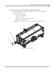
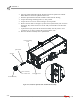
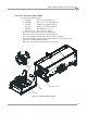
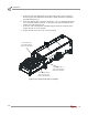
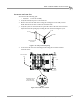
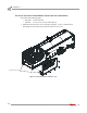
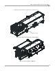
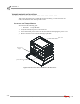
Table Of Contents
- Cover
- Copyright
- Table of Contents
- Warnings
- 1 - Specifications and Operating Requirements
- 2 - Stationary Dyno Installation
- 3 - 4WD Dyno Installation
- Unpacking and Inspecting the Dyno
- Track Assembly
- Dyno Installation
- Cable Routing
- Identifying the Cables
- Routing the Cables—Without the Eddy Current Brakes
- Wiring the Breakout Board—Without the Eddy Current Brakes
- Routing the Cables—With One Eddy Current Brake
- Wiring the Breakout Board—With One Eddy Current Brake
- Routing the Cables—With Two Eddy Current Brakes
- Wiring the Advanced Breakout Board—With Two Eddy Current Brakes
- Hydraulic Movement Installation
- Air Can Sleeve
- 4WD Dyno Movement Test
- Bridge Installation—Stationary Dyno
- Bridge Installation—4WD Dyno
- Deck Installation
- Logo Panel Installation
- 4 - Eddy Current Brake Installation
- Eddy Current Brake Installation
- Before Installing the Eddy Current Brake: Verify Optimal Brake Cooling
- Before Installing the Eddy Current Brake: Verify Mounting Holes
- Unpacking the Eddy Current Brake
- Installing the Temperature Sensor
- Installing the Bearing, Splined Shaft, and Driveline Assembly
- Installing the Eddy Current Brake
- Installing the Load Cell
- Installing the Front and Rear Brake Covers and Theta Controller
- Torque Module Installation
- Load Cell Calibration
- Eddy Current Brake Installation
- 5 - Side Deck Assembly Installation
- 6 - Basic Dyno Operation
- A - Red Head Anchor Installation
- B - Power Requirements and Installation
- C - Stationary Dyno Upgrade
- D - Bridge Extension Assembly
- E - Interface Roller Assembly Installation
- F - Torque Values
- Index
Above Ground Model 424x/424xLC
2
Automotive Dynamometer Installation Guide
CHAPTER 4
Eddy Current Brake Installation
4-10
2 Insert the splined shaft through the bearing and into the spline hub of drum.
Note: Make sure the short splined end faces out.
3 Push the splined shaft in until the shoulder is flush with the bearing.
4 Torque the bearing mounting bolts to 57 foot-pounds.
5 Torque the two set screws on the bearing to 25 foot-pounds.
6 Remove the four bolts securing the u-joint to the keyed driveline yoke. Set these
bolts aside; they will be used to secure the eddy current brake to the driveline
assembly.
7 Separate the keyed yoke from the driveline assembly. You may need to use a
screwdriver or pry bar to separate the u-joint from the yoke.
8 Place the driveline assembly on the splined shaft.
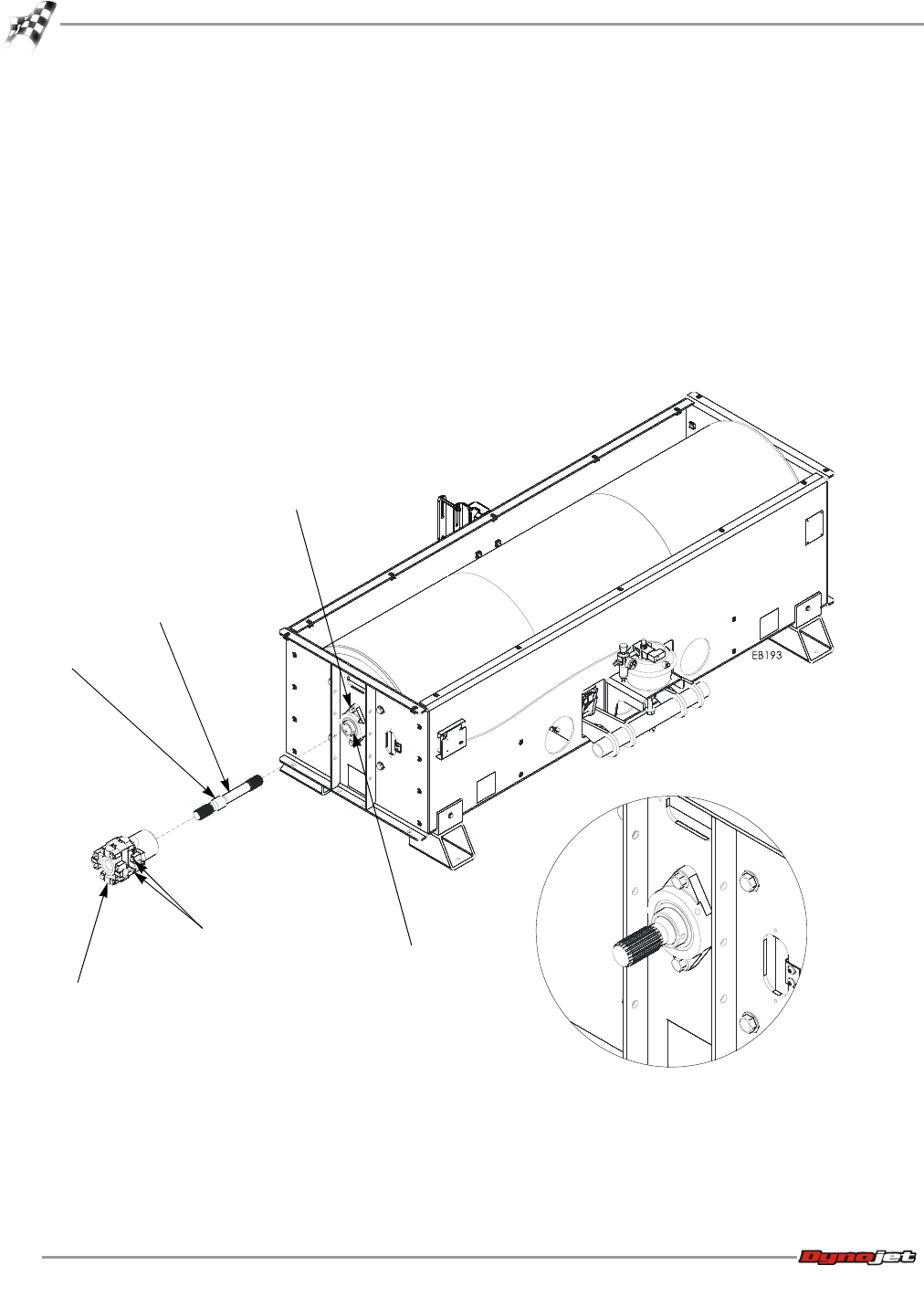
Figure 4-10: Install the Splined Shaft and Driveline Assembly
driveline assembly
splined shaft
bearing set screws
bearing mounting
bolts
remove four bolts,
two on either side
shoulder