
Installation Guide Owner's manual
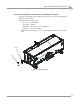
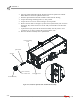
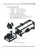
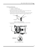
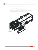
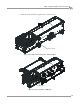
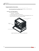
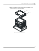

Table Of Contents
- Cover
- Copyright
- Table of Contents
- Warnings
- 1 - Specifications and Operating Requirements
- 2 - Stationary Dyno Installation
- 3 - 4WD Dyno Installation
- Unpacking and Inspecting the Dyno
- Track Assembly
- Dyno Installation
- Cable Routing
- Identifying the Cables
- Routing the Cables—Without the Eddy Current Brakes
- Wiring the Breakout Board—Without the Eddy Current Brakes
- Routing the Cables—With One Eddy Current Brake
- Wiring the Breakout Board—With One Eddy Current Brake
- Routing the Cables—With Two Eddy Current Brakes
- Wiring the Advanced Breakout Board—With Two Eddy Current Brakes
- Hydraulic Movement Installation
- Air Can Sleeve
- 4WD Dyno Movement Test
- Bridge Installation—Stationary Dyno
- Bridge Installation—4WD Dyno
- Deck Installation
- Logo Panel Installation
- 4 - Eddy Current Brake Installation
- Eddy Current Brake Installation
- Before Installing the Eddy Current Brake: Verify Optimal Brake Cooling
- Before Installing the Eddy Current Brake: Verify Mounting Holes
- Unpacking the Eddy Current Brake
- Installing the Temperature Sensor
- Installing the Bearing, Splined Shaft, and Driveline Assembly
- Installing the Eddy Current Brake
- Installing the Load Cell
- Installing the Front and Rear Brake Covers and Theta Controller
- Torque Module Installation
- Load Cell Calibration
- Eddy Current Brake Installation
- 5 - Side Deck Assembly Installation
- 6 - Basic Dyno Operation
- A - Red Head Anchor Installation
- B - Power Requirements and Installation
- C - Stationary Dyno Upgrade
- D - Bridge Extension Assembly
- E - Interface Roller Assembly Installation
- F - Torque Values
- Index
EDDY CURRENT BRAKE INSTALLATION
Eddy Current Brake Installation
Version 8 Above Ground Model 424x/424xLC
2
Automotive Dynamometer Installation Guide
4-13
INSTALLING THE LOAD CELL
You will need the following part:
• 76950505 Load Cell Assembly
1 Verify the main dyno power is disconnected.
2 Remove the two bolts and nuts securing the existing bar on the eddy current
brake and remove the bar. Set the bolts and nuts aside.
3 Verify the eyelets on the load cell are spaced the same as the bar removed earlier.
Adjust the load cell spacing by loosening the lock nut and turning the eyelet.
Figure 4-13: Verify Load Cell Spacing
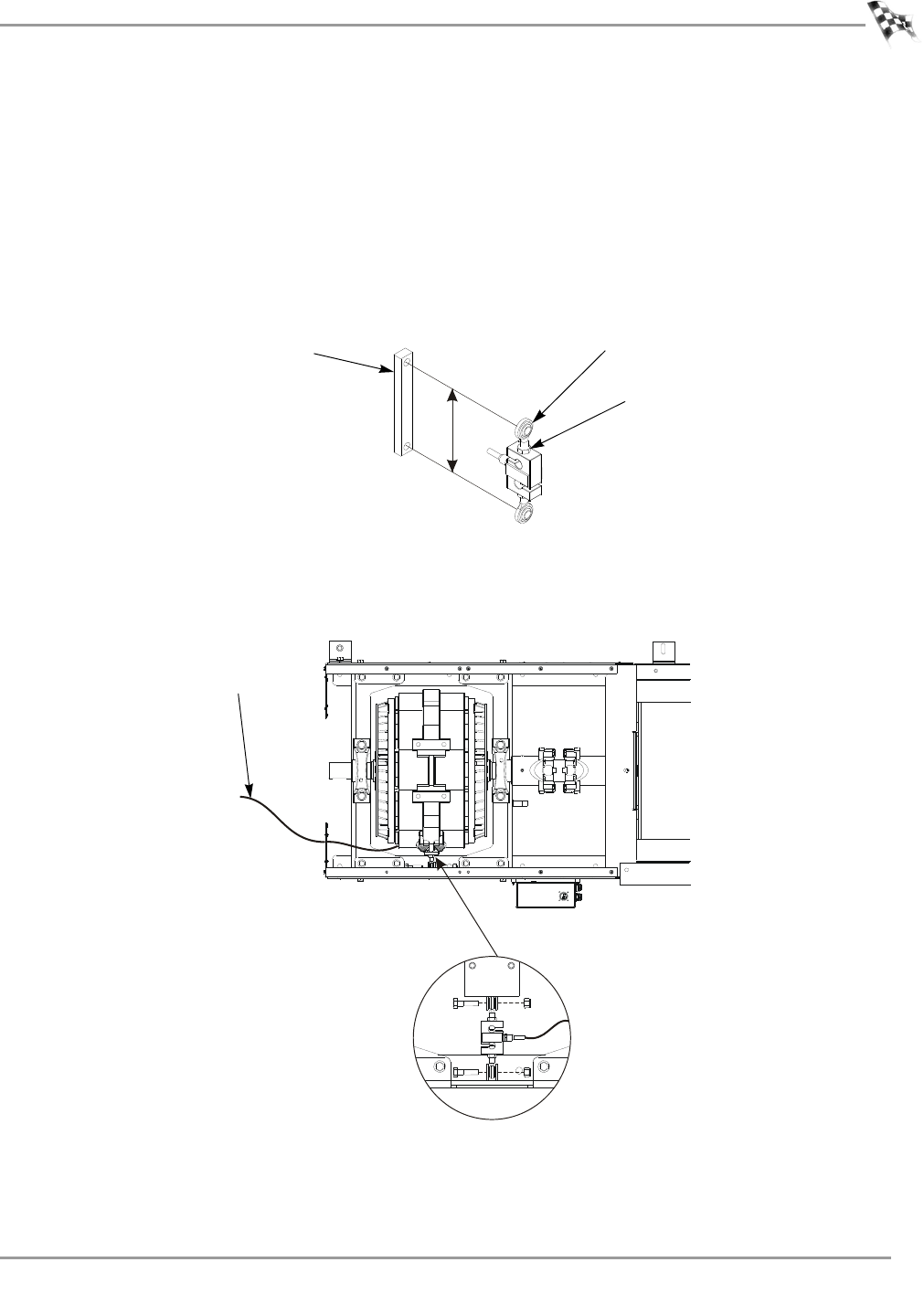
4 Secure the load cell to the mounting bracket using the two bolts and nuts
removed earlier.
Figure 4-14: Install the Load Cell
distance must be
the same
eyelet
bar
lock nut
TM057
install the load cell
(the brake is not
shown for clarity)
load cell cable
dyno