
Installation Guide Owner's manual
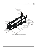
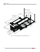
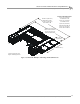
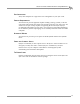
Table Of Contents
- Cover
- Copyright
- Table of Contents
- Warnings
- 1 - Specifications and Operating Requirements
- 2 - Stationary Dyno Installation
- 3 - 4WD Dyno Installation
- Unpacking and Inspecting the Dyno
- Track Assembly
- Dyno Installation
- Cable Routing
- Identifying the Cables
- Routing the Cables—Without the Eddy Current Brakes
- Wiring the Breakout Board—Without the Eddy Current Brakes
- Routing the Cables—With One Eddy Current Brake
- Wiring the Breakout Board—With One Eddy Current Brake
- Routing the Cables—With Two Eddy Current Brakes
- Wiring the Advanced Breakout Board—With Two Eddy Current Brakes
- Hydraulic Movement Installation
- Air Can Sleeve
- 4WD Dyno Movement Test
- Bridge Installation—Stationary Dyno
- Bridge Installation—4WD Dyno
- Deck Installation
- Logo Panel Installation
- 4 - Eddy Current Brake Installation
- Eddy Current Brake Installation
- Before Installing the Eddy Current Brake: Verify Optimal Brake Cooling
- Before Installing the Eddy Current Brake: Verify Mounting Holes
- Unpacking the Eddy Current Brake
- Installing the Temperature Sensor
- Installing the Bearing, Splined Shaft, and Driveline Assembly
- Installing the Eddy Current Brake
- Installing the Load Cell
- Installing the Front and Rear Brake Covers and Theta Controller
- Torque Module Installation
- Load Cell Calibration
- Eddy Current Brake Installation
- 5 - Side Deck Assembly Installation
- 6 - Basic Dyno Operation
- A - Red Head Anchor Installation
- B - Power Requirements and Installation
- C - Stationary Dyno Upgrade
- D - Bridge Extension Assembly
- E - Interface Roller Assembly Installation
- F - Torque Values
- Index

Above Ground Model 424x/424xLC
2
Automotive Dynamometer Installation Guide
1-1
C HAPTER
1
S
PECIFICATIONS
AND
O
PERATING
R
EQUIREMENTS
Thank you for purchasing Dynojet’s Above Ground Model 424x/424xLC
2
Automotive
Dynamometer (dyno). Dynojet’s software and dynamometers will give you the power
to get the maximum performance out of the vehicles you evaluate. Whether you are
new to the benefits of a chassis dynamometer or an experienced performance leader,
the repeatability and diagnostic tools of WinPEP 7 software and a Dynojet
dynamometer will give you the professional results you are looking for.
This document provides instructions for installing the stationary dyno, the four wheel
drive (4WD) dyno, and the eddy current brakes. This document will walk you through
operating requirements, hardware installation, electronics set up, and basic dyno
operation. To ensure safety and accuracy in the procedures, perform the procedures
as they are described.
Document Part Number: 98210109
Version 8
Last Updated: 01-25-13
This chapter is divided into the following categories:
•Introduction, page 1-2
• Dynamometer Specifications and Requirements, page 1-4
• Model 424 Stationary and 4WD Dynamometer, page 1-10
• Model 424 4WD Dynamometer with Bridge and Deck, page 1-11
• Dyno Electronics, page 1-12
• Lift Specifications and Requirements, page 1-13