
Installation Guide Owner's manual
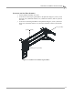
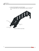
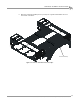

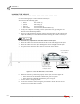
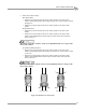
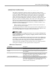
Table Of Contents
- Cover
- Copyright
- Table of Contents
- Warnings
- 1 - Specifications and Operating Requirements
- 2 - Stationary Dyno Installation
- 3 - 4WD Dyno Installation
- Unpacking and Inspecting the Dyno
- Track Assembly
- Dyno Installation
- Cable Routing
- Identifying the Cables
- Routing the Cables—Without the Eddy Current Brakes
- Wiring the Breakout Board—Without the Eddy Current Brakes
- Routing the Cables—With One Eddy Current Brake
- Wiring the Breakout Board—With One Eddy Current Brake
- Routing the Cables—With Two Eddy Current Brakes
- Wiring the Advanced Breakout Board—With Two Eddy Current Brakes
- Hydraulic Movement Installation
- Air Can Sleeve
- 4WD Dyno Movement Test
- Bridge Installation—Stationary Dyno
- Bridge Installation—4WD Dyno
- Deck Installation
- Logo Panel Installation
- 4 - Eddy Current Brake Installation
- Eddy Current Brake Installation
- Before Installing the Eddy Current Brake: Verify Optimal Brake Cooling
- Before Installing the Eddy Current Brake: Verify Mounting Holes
- Unpacking the Eddy Current Brake
- Installing the Temperature Sensor
- Installing the Bearing, Splined Shaft, and Driveline Assembly
- Installing the Eddy Current Brake
- Installing the Load Cell
- Installing the Front and Rear Brake Covers and Theta Controller
- Torque Module Installation
- Load Cell Calibration
- Eddy Current Brake Installation
- 5 - Side Deck Assembly Installation
- 6 - Basic Dyno Operation
- A - Red Head Anchor Installation
- B - Power Requirements and Installation
- C - Stationary Dyno Upgrade
- D - Bridge Extension Assembly
- E - Interface Roller Assembly Installation
- F - Torque Values
- Index
Above Ground Model 424x/424xLC
2
Automotive Dynamometer Installation Guide
CHAPTER 6
Loading the Vehicle
6-2
. . . . . . . . . . . . . . . . . . . . . . . . . . . . . . . . . . .
LOADING THE VEHICLE
Use the following steps to load a vehicle on the dyno.
You will need the following parts:
• 2A092 Tire Chock (4)
• 30AS21 Axle Strap (4)
• 500-C10 Car Tie-Down (4)
• 500-C10W/S Car Tie-Down, Hi-Performance (2)
1 Verify your computer is running. Set the dyno brake on by pressing the red
button on the hand-held pendant.
2 For four or all-wheel drive vehicles, measure the wheel base on the vehicle and
adjust the 4WD dyno to that dimension before driving the vehicle on the dyno.
Do not make any adjustments with the vehicle on the dyno.
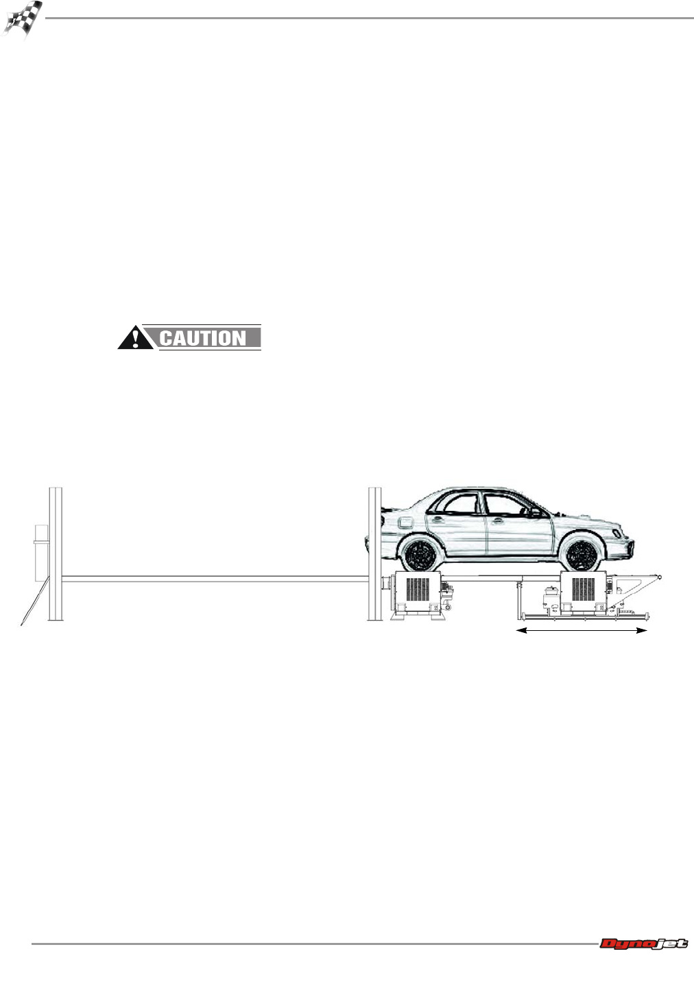
3 Drive the vehicle onto the lift and raise the lift to the same height as the dyno.
4 Drive the vehicle onto the dyno and align the vehicle straight with the dyno.
5 Stop the vehicle when the drive axles are centered on the drums.
Figure 6-1: Center the Drive Axles on the Drums
6 When the vehicle is positioned properly on the dyno, shut the engine off.
• If the vehicle has an automatic transmission, place it in park.
• If the vehicle has a manual transmission, place it in gear.
7 Set the vehicle’s emergency brake.
8 Secure the non-drive wheels using the provided tire chocks. Do not use tire
chocks for four wheel drive vehicles.
adjust wheel base of 4wd dyno
before loading the vehicle
center drive axle on
both dyno drums
four or all-wheel
drive vehicles
lift