
Installation Guide Owner's manual
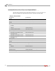
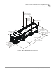
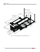
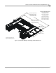
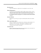
Table Of Contents
- Cover
- Copyright
- Table of Contents
- Warnings
- 1 - Specifications and Operating Requirements
- 2 - Stationary Dyno Installation
- 3 - 4WD Dyno Installation
- Unpacking and Inspecting the Dyno
- Track Assembly
- Dyno Installation
- Cable Routing
- Identifying the Cables
- Routing the Cables—Without the Eddy Current Brakes
- Wiring the Breakout Board—Without the Eddy Current Brakes
- Routing the Cables—With One Eddy Current Brake
- Wiring the Breakout Board—With One Eddy Current Brake
- Routing the Cables—With Two Eddy Current Brakes
- Wiring the Advanced Breakout Board—With Two Eddy Current Brakes
- Hydraulic Movement Installation
- Air Can Sleeve
- 4WD Dyno Movement Test
- Bridge Installation—Stationary Dyno
- Bridge Installation—4WD Dyno
- Deck Installation
- Logo Panel Installation
- 4 - Eddy Current Brake Installation
- Eddy Current Brake Installation
- Before Installing the Eddy Current Brake: Verify Optimal Brake Cooling
- Before Installing the Eddy Current Brake: Verify Mounting Holes
- Unpacking the Eddy Current Brake
- Installing the Temperature Sensor
- Installing the Bearing, Splined Shaft, and Driveline Assembly
- Installing the Eddy Current Brake
- Installing the Load Cell
- Installing the Front and Rear Brake Covers and Theta Controller
- Torque Module Installation
- Load Cell Calibration
- Eddy Current Brake Installation
- 5 - Side Deck Assembly Installation
- 6 - Basic Dyno Operation
- A - Red Head Anchor Installation
- B - Power Requirements and Installation
- C - Stationary Dyno Upgrade
- D - Bridge Extension Assembly
- E - Interface Roller Assembly Installation
- F - Torque Values
- Index

Above Ground Model 424x/424xLC
2
Automotive Dynamometer Installation Guide
CHAPTER 1
Dynamometer Specifications and Requirements
1-4
. . . . . . . . . . . . . . . . . . . . . . . . . . . . . . . . . . .
DYNAMOMETER SPECIFICATIONS AND REQUIREMENTS
The following specifications and requirements will help you set up your dyno area
and verify you have the requirements necessary to operate your dyno safely.
CHASSIS SPECIFICATIONS
description specifications
Length
of frame 218.44 cm (86.00 in.)
of frame with eddy current brake 321.23 cm (126.47 in.)
Height
to top of frame 58.42 cm (23.00 in.)
to top of frame with feet/track
assembly
72.07 cm (28.375 in.)
Width
of frame 73.66 cm (29.00 in.)
including cradle assembly 130.18 cm (51.25 in.)
including air brake 93.83 cm (36.94 in.)
both frames, deck, bridge—full in 397.00 cm (156.30 in.)
both frames, deck, bridge—full in
with extension kit
422.40 cm (166.30 in.)
both frames, deck, bridge—full out 487.68 cm (192.00 in.)
both frames, deck, bridge—full out
with extension kit
513.08 cm (202.00 in.)
Track Assembly
Length 208.92 cm (82.25 in.)
Width 218.44 cm (86.00 in.)
Weight
stationary crated dyno 2,114 kg (4,660 lb.)
4WD crated dyno 2,495 kg (5,500 lb.)
Drum
diameter 60.96 cm (24.00 in.)
width 205.74 cm (81.00 in.)
Frame structural steel channel and angle
Maximum Speed 322 kph (200 mph)
Maximum Axle Weight 1361 kg (3000 lb.)
Remote Switches remote software control