
Installation Guide Owner's manual
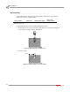
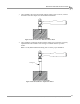

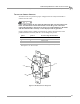
Table Of Contents
- Cover
- Copyright
- Table of Contents
- Warnings
- 1 - Specifications and Operating Requirements
- 2 - Stationary Dyno Installation
- 3 - 4WD Dyno Installation
- Unpacking and Inspecting the Dyno
- Track Assembly
- Dyno Installation
- Cable Routing
- Identifying the Cables
- Routing the Cables—Without the Eddy Current Brakes
- Wiring the Breakout Board—Without the Eddy Current Brakes
- Routing the Cables—With One Eddy Current Brake
- Wiring the Breakout Board—With One Eddy Current Brake
- Routing the Cables—With Two Eddy Current Brakes
- Wiring the Advanced Breakout Board—With Two Eddy Current Brakes
- Hydraulic Movement Installation
- Air Can Sleeve
- 4WD Dyno Movement Test
- Bridge Installation—Stationary Dyno
- Bridge Installation—4WD Dyno
- Deck Installation
- Logo Panel Installation
- 4 - Eddy Current Brake Installation
- Eddy Current Brake Installation
- Before Installing the Eddy Current Brake: Verify Optimal Brake Cooling
- Before Installing the Eddy Current Brake: Verify Mounting Holes
- Unpacking the Eddy Current Brake
- Installing the Temperature Sensor
- Installing the Bearing, Splined Shaft, and Driveline Assembly
- Installing the Eddy Current Brake
- Installing the Load Cell
- Installing the Front and Rear Brake Covers and Theta Controller
- Torque Module Installation
- Load Cell Calibration
- Eddy Current Brake Installation
- 5 - Side Deck Assembly Installation
- 6 - Basic Dyno Operation
- A - Red Head Anchor Installation
- B - Power Requirements and Installation
- C - Stationary Dyno Upgrade
- D - Bridge Extension Assembly
- E - Interface Roller Assembly Installation
- F - Torque Values
- Index
POWER REQUIREMENTS AND INSTALLATION
Power Requirements and Installation—North America, Japan, and Locations Using 60 Hz Power
Version 8 Above Ground Model 424x/424xLC
2
Automotive Dynamometer Installation Guide
B-3
TESTING FOR CORRECT VOLTAGES
You must test the receptacle for proper voltages before the eddy current brake is
connected to the outlet.
If the voltage readings do not match the following table, DO NOT connect the
brake. You must have a licensed electrician correct the power connection.
Connecting the brake to the incorrect voltage can result in damage to the brake
and will void the brake warranty. Contact Dynojet with any questions.
Using a voltmeter that is capable of measuring AC voltage, measure between the
points listed below and verify that the correct voltages are present.
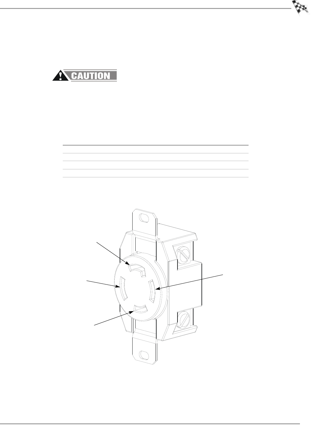
Figure B-1: Dedicated Power Receptacle
probe 1 probe 2 desired voltage measurement
2 4 216V to 260V*
1 4 108V to 130V
1 2 108V to 130V
3box<5V
*If using two of the three-phase lines of a 120/208 V 3 phase Y system,
then expect to see 187V to 225V.
4 (X)
1 (W)
2 (Y)
3 (G)