
Installation Guide Owner's manual

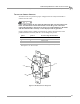
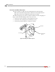
Table Of Contents
- Cover
- Copyright
- Table of Contents
- Warnings
- 1 - Specifications and Operating Requirements
- 2 - Stationary Dyno Installation
- 3 - 4WD Dyno Installation
- Unpacking and Inspecting the Dyno
- Track Assembly
- Dyno Installation
- Cable Routing
- Identifying the Cables
- Routing the Cables—Without the Eddy Current Brakes
- Wiring the Breakout Board—Without the Eddy Current Brakes
- Routing the Cables—With One Eddy Current Brake
- Wiring the Breakout Board—With One Eddy Current Brake
- Routing the Cables—With Two Eddy Current Brakes
- Wiring the Advanced Breakout Board—With Two Eddy Current Brakes
- Hydraulic Movement Installation
- Air Can Sleeve
- 4WD Dyno Movement Test
- Bridge Installation—Stationary Dyno
- Bridge Installation—4WD Dyno
- Deck Installation
- Logo Panel Installation
- 4 - Eddy Current Brake Installation
- Eddy Current Brake Installation
- Before Installing the Eddy Current Brake: Verify Optimal Brake Cooling
- Before Installing the Eddy Current Brake: Verify Mounting Holes
- Unpacking the Eddy Current Brake
- Installing the Temperature Sensor
- Installing the Bearing, Splined Shaft, and Driveline Assembly
- Installing the Eddy Current Brake
- Installing the Load Cell
- Installing the Front and Rear Brake Covers and Theta Controller
- Torque Module Installation
- Load Cell Calibration
- Eddy Current Brake Installation
- 5 - Side Deck Assembly Installation
- 6 - Basic Dyno Operation
- A - Red Head Anchor Installation
- B - Power Requirements and Installation
- C - Stationary Dyno Upgrade
- D - Bridge Extension Assembly
- E - Interface Roller Assembly Installation
- F - Torque Values
- Index

Above Ground Model 424x/424xLC
2
Automotive Dynamometer Installation Guide
APPENDIX B
Power Requirements and Installation—North America, Japan, and Locations Using 60 Hz Power
B-4
HARD WIRING TO THE BUILDING
Use the following instructions to wire the brake directly to the building.
The brake must connect to a two pole disconnect switch to allow the removal of all
power to the brake for servicing. This box may contain fusing, circuit breakers, or the
circuit protection may be upstream in the building power system. The circuit must be
protected to 30A with slow blow fuses or time delayed circuit breakers.
The power cord that attaches to the brake has three conductors internally and their
colors are white, black, and green.
1 Remove the brake power plug and connect 240VAC single-phase between the
black and the white wires through the disconnect switch.
2 Connect the green wire to the ground connection.
3 Refer to the previous table for testing and probe the new connections as follows:
• white wire as location #2
• black wire as location #4
• green wire as location #3