
Installation Guide Owner's manual

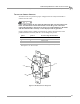
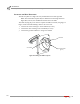
Table Of Contents
- Cover
- Copyright
- Table of Contents
- Warnings
- 1 - Specifications and Operating Requirements
- 2 - Stationary Dyno Installation
- 3 - 4WD Dyno Installation
- Unpacking and Inspecting the Dyno
- Track Assembly
- Dyno Installation
- Cable Routing
- Identifying the Cables
- Routing the Cables—Without the Eddy Current Brakes
- Wiring the Breakout Board—Without the Eddy Current Brakes
- Routing the Cables—With One Eddy Current Brake
- Wiring the Breakout Board—With One Eddy Current Brake
- Routing the Cables—With Two Eddy Current Brakes
- Wiring the Advanced Breakout Board—With Two Eddy Current Brakes
- Hydraulic Movement Installation
- Air Can Sleeve
- 4WD Dyno Movement Test
- Bridge Installation—Stationary Dyno
- Bridge Installation—4WD Dyno
- Deck Installation
- Logo Panel Installation
- 4 - Eddy Current Brake Installation
- Eddy Current Brake Installation
- Before Installing the Eddy Current Brake: Verify Optimal Brake Cooling
- Before Installing the Eddy Current Brake: Verify Mounting Holes
- Unpacking the Eddy Current Brake
- Installing the Temperature Sensor
- Installing the Bearing, Splined Shaft, and Driveline Assembly
- Installing the Eddy Current Brake
- Installing the Load Cell
- Installing the Front and Rear Brake Covers and Theta Controller
- Torque Module Installation
- Load Cell Calibration
- Eddy Current Brake Installation
- 5 - Side Deck Assembly Installation
- 6 - Basic Dyno Operation
- A - Red Head Anchor Installation
- B - Power Requirements and Installation
- C - Stationary Dyno Upgrade
- D - Bridge Extension Assembly
- E - Interface Roller Assembly Installation
- F - Torque Values
- Index
POWER REQUIREMENTS AND INSTALLATION
Power Requirements and Installation—Excluding North America and Japan
Version 8 Above Ground Model 424x/424xLC
2
Automotive Dynamometer Installation Guide
B-5
POWER REQUIREMENTS AND INSTALLATION—EXCLUDING NORTH AMERICA AND
. . . . . . . . . . . . . . . . . . . . . . . . . . . . . . . . . . .
JAPAN
The eddy current brake (excluding North America and Japan) requires a dedicated
wall receptacle which must be wired for operation and is included with the brake or
may be shipped in advanced in a separate package. The brake is equipped with a
twenty-five foot power cord with a twist lock plug pre-wired on the end.
The brake requires a dedicated 240VAC single-phase power outlet rated for 30A for
proper operation. Failure to follow these instructions could result in personal
injury or damage to the brake. Connecting the brake to the incorrect voltage will
void the brake warranty. Contact Dynojet with any questions.
The dedicated wall receptacle is a three-pin IEC grounded 30A type and must be
wired in accordance with local building codes and requirements. Installation may
require a licensed electrician to conform to applicable safety standards.
If you are installing your brake in a location other than North America or Japan
and the brake is not equipped with a three pin IEC grounded plug, contact
Dynojet before attempting to connect the brake.
Local and national electrical codes will require that the box containing the receptacle
is grounded.
• This circuit should have a dedicated 30A double-pole circuit breaker.
• The brake should be the only device connected to this circuit.