
Installation Guide Owner's manual
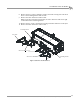
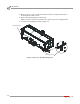
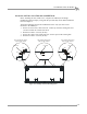
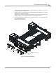
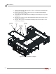

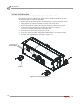
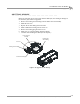

Table Of Contents
- Cover
- Copyright
- Table of Contents
- Warnings
- 1 - Specifications and Operating Requirements
- 2 - Stationary Dyno Installation
- 3 - 4WD Dyno Installation
- Unpacking and Inspecting the Dyno
- Track Assembly
- Dyno Installation
- Cable Routing
- Identifying the Cables
- Routing the Cables—Without the Eddy Current Brakes
- Wiring the Breakout Board—Without the Eddy Current Brakes
- Routing the Cables—With One Eddy Current Brake
- Wiring the Breakout Board—With One Eddy Current Brake
- Routing the Cables—With Two Eddy Current Brakes
- Wiring the Advanced Breakout Board—With Two Eddy Current Brakes
- Hydraulic Movement Installation
- Air Can Sleeve
- 4WD Dyno Movement Test
- Bridge Installation—Stationary Dyno
- Bridge Installation—4WD Dyno
- Deck Installation
- Logo Panel Installation
- 4 - Eddy Current Brake Installation
- Eddy Current Brake Installation
- Before Installing the Eddy Current Brake: Verify Optimal Brake Cooling
- Before Installing the Eddy Current Brake: Verify Mounting Holes
- Unpacking the Eddy Current Brake
- Installing the Temperature Sensor
- Installing the Bearing, Splined Shaft, and Driveline Assembly
- Installing the Eddy Current Brake
- Installing the Load Cell
- Installing the Front and Rear Brake Covers and Theta Controller
- Torque Module Installation
- Load Cell Calibration
- Eddy Current Brake Installation
- 5 - Side Deck Assembly Installation
- 6 - Basic Dyno Operation
- A - Red Head Anchor Installation
- B - Power Requirements and Installation
- C - Stationary Dyno Upgrade
- D - Bridge Extension Assembly
- E - Interface Roller Assembly Installation
- F - Torque Values
- Index
STATIONARY DYNO UPGRADE
Deck Relocation
Version 8 Above Ground Model 424x/424xLC
2
Automotive Dynamometer Installation Guide
C-11
INSTALLING THE EARLY STYLE DECK ON THE 4WD DYNO
Before installing the deck, make sure to complete the 4WD dyno and bridge
installation found in Chapter 3 along with the optional eddy current brake installation
found in Chapter 4.
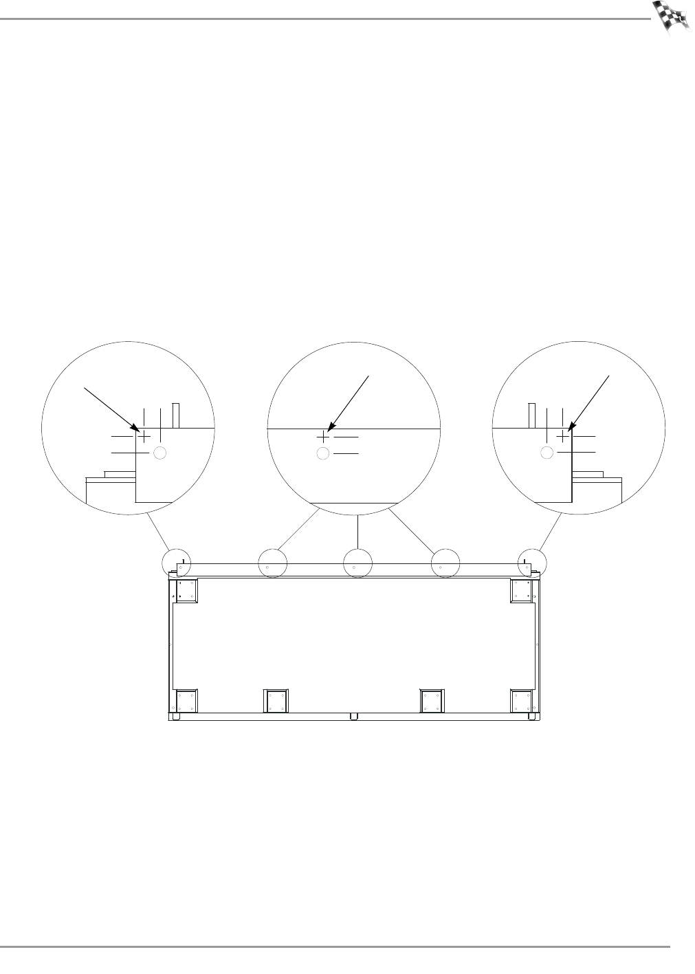
The deck mounting holes must be modified before the early style deck can be
mounted to the 4WD dyno.
1 For the two outer holes, mark each hole .5-inches up from the existing hole and
.5-inches towards the outside of the deck.
2 Drill the new holes 7/16-inch (10 mm).
3 For the three inner holes, mark each hole .5-inches up from the existing hole.
4 Drill the new holes 7/16-inch (10 mm).
Figure C-10: Modify the Deck Mounting Holes
AD106
.5 in.
new hole
outer existing hole shown
with new hole marked
.5 in.
.5 in.
.5 in.
.5 in.
outer existing hole shown
with new hole marked
new hole
outer existing hole shown
with new hole marked
new hole