
Installation Guide Owner's manual
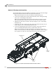
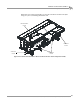
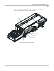

Table Of Contents
- Cover
- Copyright
- Table of Contents
- Warnings
- 1 - Specifications and Operating Requirements
- 2 - Stationary Dyno Installation
- 3 - 4WD Dyno Installation
- Unpacking and Inspecting the Dyno
- Track Assembly
- Dyno Installation
- Cable Routing
- Identifying the Cables
- Routing the Cables—Without the Eddy Current Brakes
- Wiring the Breakout Board—Without the Eddy Current Brakes
- Routing the Cables—With One Eddy Current Brake
- Wiring the Breakout Board—With One Eddy Current Brake
- Routing the Cables—With Two Eddy Current Brakes
- Wiring the Advanced Breakout Board—With Two Eddy Current Brakes
- Hydraulic Movement Installation
- Air Can Sleeve
- 4WD Dyno Movement Test
- Bridge Installation—Stationary Dyno
- Bridge Installation—4WD Dyno
- Deck Installation
- Logo Panel Installation
- 4 - Eddy Current Brake Installation
- Eddy Current Brake Installation
- Before Installing the Eddy Current Brake: Verify Optimal Brake Cooling
- Before Installing the Eddy Current Brake: Verify Mounting Holes
- Unpacking the Eddy Current Brake
- Installing the Temperature Sensor
- Installing the Bearing, Splined Shaft, and Driveline Assembly
- Installing the Eddy Current Brake
- Installing the Load Cell
- Installing the Front and Rear Brake Covers and Theta Controller
- Torque Module Installation
- Load Cell Calibration
- Eddy Current Brake Installation
- 5 - Side Deck Assembly Installation
- 6 - Basic Dyno Operation
- A - Red Head Anchor Installation
- B - Power Requirements and Installation
- C - Stationary Dyno Upgrade
- D - Bridge Extension Assembly
- E - Interface Roller Assembly Installation
- F - Torque Values
- Index
Above Ground Model 424x/424xLC
2
Automotive Dynamometer Installation Guide
APPENDIX D
Bridge Extension Installation
D-2
. . . . . . . . . . . . . . . . . . . . . . . . . . . . . . . . . . .
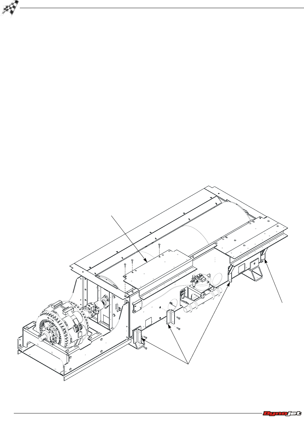
BRIDGE EXTENSION INSTALLATION
The optional bridge extension assembly (P/N 61119183) is used to extend the bridge
range from an 88-130 inch wheel base to a 98-140 inch wheel base.
Note: The Linx option can not be used with the extended wheel base.
1 Secure the extended runner mount (z-shaped bracket) to the drum guard using
three 3/8 x 1.5-inch flange hex allen bolts.
Note: The extended runner mounts used with the bridge extension are longer
than the standard runner mounts. Be sure to use the correct runner mounts.
2 Install the two inner brace mounts to the dyno using two 3/8 x 1.5-inch flange
head bolts each.
3 Secure the outer brace mount to the side of the dyno without the eddy current
brake using two 3/8 x 1.5-inch flange head bolts each.
4 Secure the remaining inner brace mount to the eddy current brake using two
3/8 x 1.5-inch flange head bolts and two 3/8-inch nylock nuts each.
Note: If you do not have an eddy current brake, you will use an outer brace
mount. Secure this directly to the dyno using the same hardware. Refer to Figure
D-2 on page D-3. In this case, there will be one left over inner brace mount.
Figure D-1: Install the Extended Runner Mount and Brace Mount
AD166
extended runner
mount
outer brace
mount
inner brace
mount