
Installation Guide Owner's manual
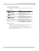
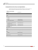
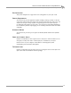
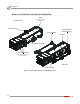
Table Of Contents
- Cover
- Copyright
- Table of Contents
- Warnings
- 1 - Specifications and Operating Requirements
- 2 - Stationary Dyno Installation
- 3 - 4WD Dyno Installation
- Unpacking and Inspecting the Dyno
- Track Assembly
- Dyno Installation
- Cable Routing
- Identifying the Cables
- Routing the Cables—Without the Eddy Current Brakes
- Wiring the Breakout Board—Without the Eddy Current Brakes
- Routing the Cables—With One Eddy Current Brake
- Wiring the Breakout Board—With One Eddy Current Brake
- Routing the Cables—With Two Eddy Current Brakes
- Wiring the Advanced Breakout Board—With Two Eddy Current Brakes
- Hydraulic Movement Installation
- Air Can Sleeve
- 4WD Dyno Movement Test
- Bridge Installation—Stationary Dyno
- Bridge Installation—4WD Dyno
- Deck Installation
- Logo Panel Installation
- 4 - Eddy Current Brake Installation
- Eddy Current Brake Installation
- Before Installing the Eddy Current Brake: Verify Optimal Brake Cooling
- Before Installing the Eddy Current Brake: Verify Mounting Holes
- Unpacking the Eddy Current Brake
- Installing the Temperature Sensor
- Installing the Bearing, Splined Shaft, and Driveline Assembly
- Installing the Eddy Current Brake
- Installing the Load Cell
- Installing the Front and Rear Brake Covers and Theta Controller
- Torque Module Installation
- Load Cell Calibration
- Eddy Current Brake Installation
- 5 - Side Deck Assembly Installation
- 6 - Basic Dyno Operation
- A - Red Head Anchor Installation
- B - Power Requirements and Installation
- C - Stationary Dyno Upgrade
- D - Bridge Extension Assembly
- E - Interface Roller Assembly Installation
- F - Torque Values
- Index

Above Ground Model 424x/424xLC
2
Automotive Dynamometer Installation Guide
CHAPTER 1
Dynamometer Specifications and Requirements
1-8
COMPRESSED AIR
The following requirements are needed for the air brake:
• Clean and dry air, between 100-140 psi
• shut off valve
• 1/4-inch NPT pipe thread connector (to attach air to the dyno), if air hose does not
have a 3/8-inch inside diameter
• have a 3/8-inch inside diameter
COMPUTER SPECIFICATIONS
You will need to provide a computer system to run the WinPEP software. A complete
list of system requirements can be found in your WinPEP 7 User Guide. This manual is
included with your dyno and is also available on your WinPEP 7 CD.
DRILL AND DRILL BIT REQUIREMENTS
You will need to provide a drill and drill bit capable of drilling holes in concrete. Refer
to Appendix A for more information on installing Red Head Anchors.
• drill bit size: 1/2-inch
• minimum hole depth: 1 5/8-inch (41.2 mm)
ELECTRICAL REQUIREMENTS
The hydraulic pump/motor power source and eddy current braking power source
require user supplied grounded electrical outlets with over current and short circuit
protection. These must be accessible to the operator to be used as a disconnect.
ENVIRONMENTAL REQUIREMENTS
description specifications
Power Requirements: 4WD electronics 100-240 VAC, 50/60 Hz
Power Requirements: dyno electronics 100-240 VAC, 50/60 Hz
Power Requirements: hydraulic motor 110 VAC, 60 Hz, 20A/240 VAC, 60 Hz, 10A
Power Requirements: computer Per computer manufacturer specifications
Power Requirements: optional eddy
current brake
240v 30amp single phase circuit for each eddy current
brake
Refer to Appendix B for more information.
description specifications
Tempe r a t ure
operating min./max 10°C/50°C (50°F/122°F)
storage min./max 0°C/70°C (32°F/158°F)
Humidity 0 to 95% non condensing