
Installation Guide Owner's manual

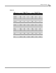
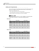

Table Of Contents
- Cover
- Copyright
- Table of Contents
- Warnings
- 1 - Specifications and Operating Requirements
- 2 - Stationary Dyno Installation
- 3 - 4WD Dyno Installation
- Unpacking and Inspecting the Dyno
- Track Assembly
- Dyno Installation
- Cable Routing
- Identifying the Cables
- Routing the Cables—Without the Eddy Current Brakes
- Wiring the Breakout Board—Without the Eddy Current Brakes
- Routing the Cables—With One Eddy Current Brake
- Wiring the Breakout Board—With One Eddy Current Brake
- Routing the Cables—With Two Eddy Current Brakes
- Wiring the Advanced Breakout Board—With Two Eddy Current Brakes
- Hydraulic Movement Installation
- Air Can Sleeve
- 4WD Dyno Movement Test
- Bridge Installation—Stationary Dyno
- Bridge Installation—4WD Dyno
- Deck Installation
- Logo Panel Installation
- 4 - Eddy Current Brake Installation
- Eddy Current Brake Installation
- Before Installing the Eddy Current Brake: Verify Optimal Brake Cooling
- Before Installing the Eddy Current Brake: Verify Mounting Holes
- Unpacking the Eddy Current Brake
- Installing the Temperature Sensor
- Installing the Bearing, Splined Shaft, and Driveline Assembly
- Installing the Eddy Current Brake
- Installing the Load Cell
- Installing the Front and Rear Brake Covers and Theta Controller
- Torque Module Installation
- Load Cell Calibration
- Eddy Current Brake Installation
- 5 - Side Deck Assembly Installation
- 6 - Basic Dyno Operation
- A - Red Head Anchor Installation
- B - Power Requirements and Installation
- C - Stationary Dyno Upgrade
- D - Bridge Extension Assembly
- E - Interface Roller Assembly Installation
- F - Torque Values
- Index

Above Ground Model 424x/424xLC
2
Automotive Dynamometer Installation Guide
APPENDIX F
Standard Bolt Torque Values
F-2
. . . . . . . . . . . . . . . . . . . . . . . . . . . . . . . . . . .
STANDARD BOLT TORQUE VALUES
Always use the torque values specified in other sections of this manual. When specific
values are not available, use the torque values listed below. Use the following
guidelines when tightening torque:
• These values are based on use of clean, dry threads.
• The following tables include values for plain finish and plated fasteners.
• Reduce torque by 10% when engine oil is used as a lubricant.
The following tables are meant to be used as guidelines for Dynojet product
torque values only. Always use caution when torquing fasteners.
GRADE 5
size torque, plain torque, plated
in-threads/in in•lb ft•lb N•m in•lb ft•lb N•m
1/4-20 101 8 11 76 6 9
1/4-28 116 10 13 87 7 10
5/16-18 209 17 24 157 13 18
5/16-24 231 19 26 173 14 20
3/8-16 371 31 42 278 23 31
3/8-24 420 35 47 315 26 36
7/16-14 593 49 67 445 37 50
7/16-20 662 55 75 497 41 56
1/2-13 905 75 102 678 57 77
1/2-20 1019 85 115 765 64 86
9/16-12 1305 109 147 979 82 111
9/16-18 1456 121 164 1092 91 123
5/8-11 1801 150 203 1351 113 153
5/8-18 2040 170 230 1530 128 173
3/4-10 3194 266 361 2395 200 271
3/4-16 3567 297 403 2675 223 302
7/8-9 5154 430 582 3866 322 437
7/8-14 5679 473 642 4259 355 481
1-8 7727 644 873 5795 483 655
1-12 8453 704 955 6340 528 716