
Installation Guide Owner's manual
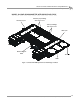

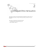
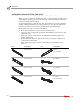
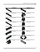
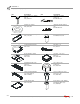
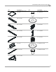
Table Of Contents
- Cover
- Copyright
- Table of Contents
- Warnings
- 1 - Specifications and Operating Requirements
- 2 - Stationary Dyno Installation
- 3 - 4WD Dyno Installation
- Unpacking and Inspecting the Dyno
- Track Assembly
- Dyno Installation
- Cable Routing
- Identifying the Cables
- Routing the Cables—Without the Eddy Current Brakes
- Wiring the Breakout Board—Without the Eddy Current Brakes
- Routing the Cables—With One Eddy Current Brake
- Wiring the Breakout Board—With One Eddy Current Brake
- Routing the Cables—With Two Eddy Current Brakes
- Wiring the Advanced Breakout Board—With Two Eddy Current Brakes
- Hydraulic Movement Installation
- Air Can Sleeve
- 4WD Dyno Movement Test
- Bridge Installation—Stationary Dyno
- Bridge Installation—4WD Dyno
- Deck Installation
- Logo Panel Installation
- 4 - Eddy Current Brake Installation
- Eddy Current Brake Installation
- Before Installing the Eddy Current Brake: Verify Optimal Brake Cooling
- Before Installing the Eddy Current Brake: Verify Mounting Holes
- Unpacking the Eddy Current Brake
- Installing the Temperature Sensor
- Installing the Bearing, Splined Shaft, and Driveline Assembly
- Installing the Eddy Current Brake
- Installing the Load Cell
- Installing the Front and Rear Brake Covers and Theta Controller
- Torque Module Installation
- Load Cell Calibration
- Eddy Current Brake Installation
- 5 - Side Deck Assembly Installation
- 6 - Basic Dyno Operation
- A - Red Head Anchor Installation
- B - Power Requirements and Installation
- C - Stationary Dyno Upgrade
- D - Bridge Extension Assembly
- E - Interface Roller Assembly Installation
- F - Torque Values
- Index
Above Ground Model 424x/424xLC
2
Automotive Dynamometer Installation Guide
CHAPTER 1
Dyno Electronics
1-12
. . . . . . . . . . . . . . . . . . . . . . . . . . . . . . . . . . .
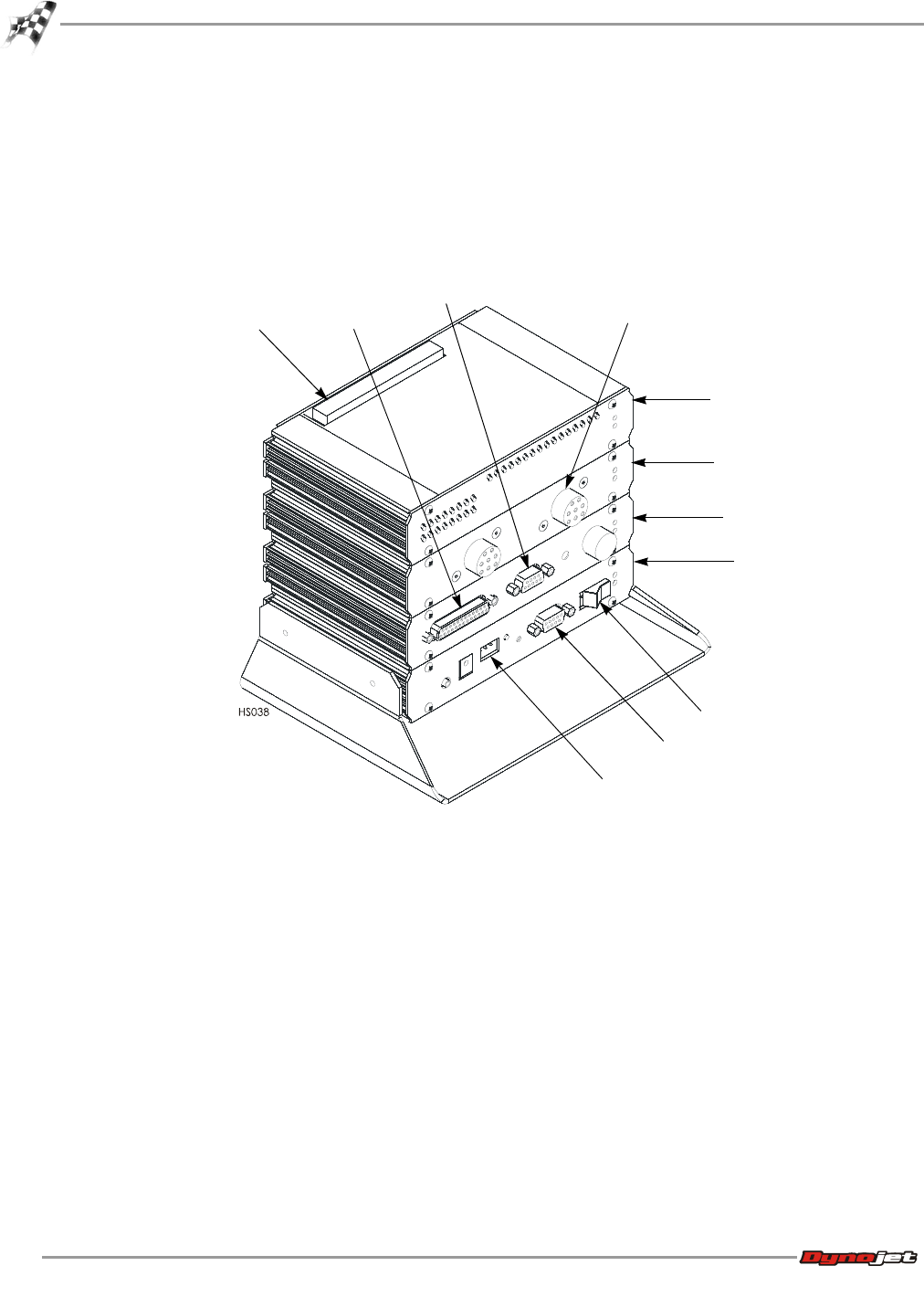
DYNO ELECTRONICS
The standard dyno electronics package is comprised of four interconnected modules.
Use the figure below to identify the modules and connectors when routing cables. A
detailed description of each module along with the instructions for connecting the
dyno electronics to the WinPEP 7 software can be found in your WinPEP 7 User Guide.
Figure 1-6: Dyno Electronics
9-pin RS-232 socket
CPU module
atmospheric
sensing module
RPM module
input/output module
9-pin hand
held pendant
3-pin power plug
system expansion
connector
inductive pickup
socket
25-pin socket
power