
Installation Guide Owner's manual
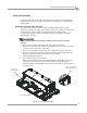
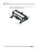
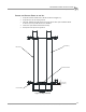
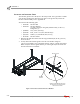
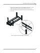
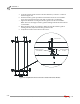
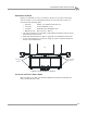

Table Of Contents
- Cover
- Copyright
- Table of Contents
- Warnings
- 1 - Specifications and Operating Requirements
- 2 - Stationary Dyno Installation
- 3 - 4WD Dyno Installation
- Unpacking and Inspecting the Dyno
- Track Assembly
- Dyno Installation
- Cable Routing
- Identifying the Cables
- Routing the Cables—Without the Eddy Current Brakes
- Wiring the Breakout Board—Without the Eddy Current Brakes
- Routing the Cables—With One Eddy Current Brake
- Wiring the Breakout Board—With One Eddy Current Brake
- Routing the Cables—With Two Eddy Current Brakes
- Wiring the Advanced Breakout Board—With Two Eddy Current Brakes
- Hydraulic Movement Installation
- Air Can Sleeve
- 4WD Dyno Movement Test
- Bridge Installation—Stationary Dyno
- Bridge Installation—4WD Dyno
- Deck Installation
- Logo Panel Installation
- 4 - Eddy Current Brake Installation
- Eddy Current Brake Installation
- Before Installing the Eddy Current Brake: Verify Optimal Brake Cooling
- Before Installing the Eddy Current Brake: Verify Mounting Holes
- Unpacking the Eddy Current Brake
- Installing the Temperature Sensor
- Installing the Bearing, Splined Shaft, and Driveline Assembly
- Installing the Eddy Current Brake
- Installing the Load Cell
- Installing the Front and Rear Brake Covers and Theta Controller
- Torque Module Installation
- Load Cell Calibration
- Eddy Current Brake Installation
- 5 - Side Deck Assembly Installation
- 6 - Basic Dyno Operation
- A - Red Head Anchor Installation
- B - Power Requirements and Installation
- C - Stationary Dyno Upgrade
- D - Bridge Extension Assembly
- E - Interface Roller Assembly Installation
- F - Torque Values
- Index
STATIONARY DYNO INSTALLATION
Dyno Installation
Version 8 Above Ground Model 424x/424xLC
2
Automotive Dynamometer Installation Guide
2-7
. . . . . . . . . . . . . . . . . . . . . . . . . . . . . . . . . . .
DYNO INSTALLATION
This section will walk you through removing the dyno from the crate and installing
the dyno in front of your lift. Refer to Appendix C for instructions on upgrading an
existing dyno.
REMOVING THE DYNO FROM THE CRATE
You will need to provide equipment capable of lifting a minimum of 2,114 kg
(4,660 lb.) to lift the dyno off the crate and into position in your dyno room. You will
also need a pair of straps capable of supporting the same weight. Dynojet
recommends using two 2-inch x 6-foot single loop style straps. Refer to “Forklift
Requirements” on page 1-7.
#
RECORD
Be sure you record the dynamometer number on the inside cover of this
manual.
1 Remove the crate braces that support the top portion of the crate.
2 Remove the four lag bolts and washers securing the dyno to the crate base using a
9/16-inch socket, open or box end wrench.
3 Remove and set aside the four flange bolts securing the crate feet to the dyno.
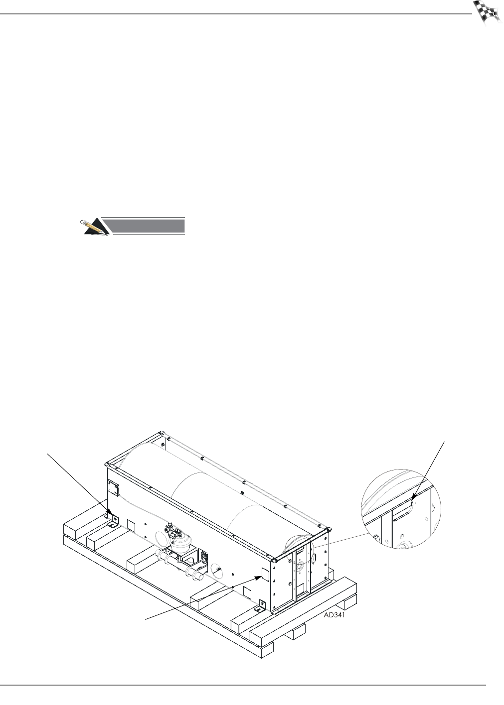
4 Route the loop strap through the opening in the dyno frame and through itself.
Pull the strap tight. Do this on each side of the dyno frame.
5 Push the forklift forks together.
6 Place each loop strap over both forks.
Note: The straps must be the same length and meet in the middle. Verify each
loop strap is over both forks to prevent the forks from being pulled apart.
7 Using the forklift, carefully lift the dyno off the crate and move it into position in
your dyno room.
Figure 2-1: Loop Strap Placement
place strap through
opening in dyno frame
dyno number
remove feet
set aside bolts