
Installation Guide Owner's manual
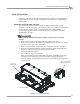
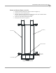
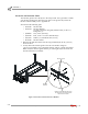
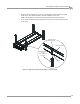
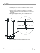

Table Of Contents
- Cover
- Copyright
- Table of Contents
- Warnings
- 1 - Specifications and Operating Requirements
- 2 - Stationary Dyno Installation
- 3 - 4WD Dyno Installation
- Unpacking and Inspecting the Dyno
- Track Assembly
- Dyno Installation
- Cable Routing
- Identifying the Cables
- Routing the Cables—Without the Eddy Current Brakes
- Wiring the Breakout Board—Without the Eddy Current Brakes
- Routing the Cables—With One Eddy Current Brake
- Wiring the Breakout Board—With One Eddy Current Brake
- Routing the Cables—With Two Eddy Current Brakes
- Wiring the Advanced Breakout Board—With Two Eddy Current Brakes
- Hydraulic Movement Installation
- Air Can Sleeve
- 4WD Dyno Movement Test
- Bridge Installation—Stationary Dyno
- Bridge Installation—4WD Dyno
- Deck Installation
- Logo Panel Installation
- 4 - Eddy Current Brake Installation
- Eddy Current Brake Installation
- Before Installing the Eddy Current Brake: Verify Optimal Brake Cooling
- Before Installing the Eddy Current Brake: Verify Mounting Holes
- Unpacking the Eddy Current Brake
- Installing the Temperature Sensor
- Installing the Bearing, Splined Shaft, and Driveline Assembly
- Installing the Eddy Current Brake
- Installing the Load Cell
- Installing the Front and Rear Brake Covers and Theta Controller
- Torque Module Installation
- Load Cell Calibration
- Eddy Current Brake Installation
- 5 - Side Deck Assembly Installation
- 6 - Basic Dyno Operation
- A - Red Head Anchor Installation
- B - Power Requirements and Installation
- C - Stationary Dyno Upgrade
- D - Bridge Extension Assembly
- E - Interface Roller Assembly Installation
- F - Torque Values
- Index
Above Ground Model 424x/424xLC
2
Automotive Dynamometer Installation Guide
CHAPTER 2
Dyno Installation
2-10
INSTALLING THE INTERFACE GUIDE
The interface guide secures the dyno to the four-post lift. It is a good idea to install
your interface guide before anchoring your dyno to the ground. If you have the
interface roller assembly, refer to Appendix E.
You will need the following parts:
• 21600000 Interface Bar
• 21600001 Interface Bracket
secured to the dyno using P/N 36582471 Bolt, 3/8-16 x 1.5",
Flange-Hex (2)
• 36488100 Nut, 3/8-16, Nylock (2)
• 36500000 Bolt, 3/8-16 x 4.5", Hex, Full Thread (2)
• 36923100 Washer, 3/8", Hardened, Flat, Steel (4)
• 61100000 Interface Guide
1 Raise the lift until the bottom of the lift is approximately 86.36 cm (34.00 in.)
above the floor.
2 Loosely attach the interface guide to the lift cross member using two
3/8-16 x 4.5-inch bolts, four 3/8-inch flat washers, and two 3/8-inch nylock nuts.
Note: Verify the interface guide with the pin is facing the dyno and is near the
bottom of the lift cross member.
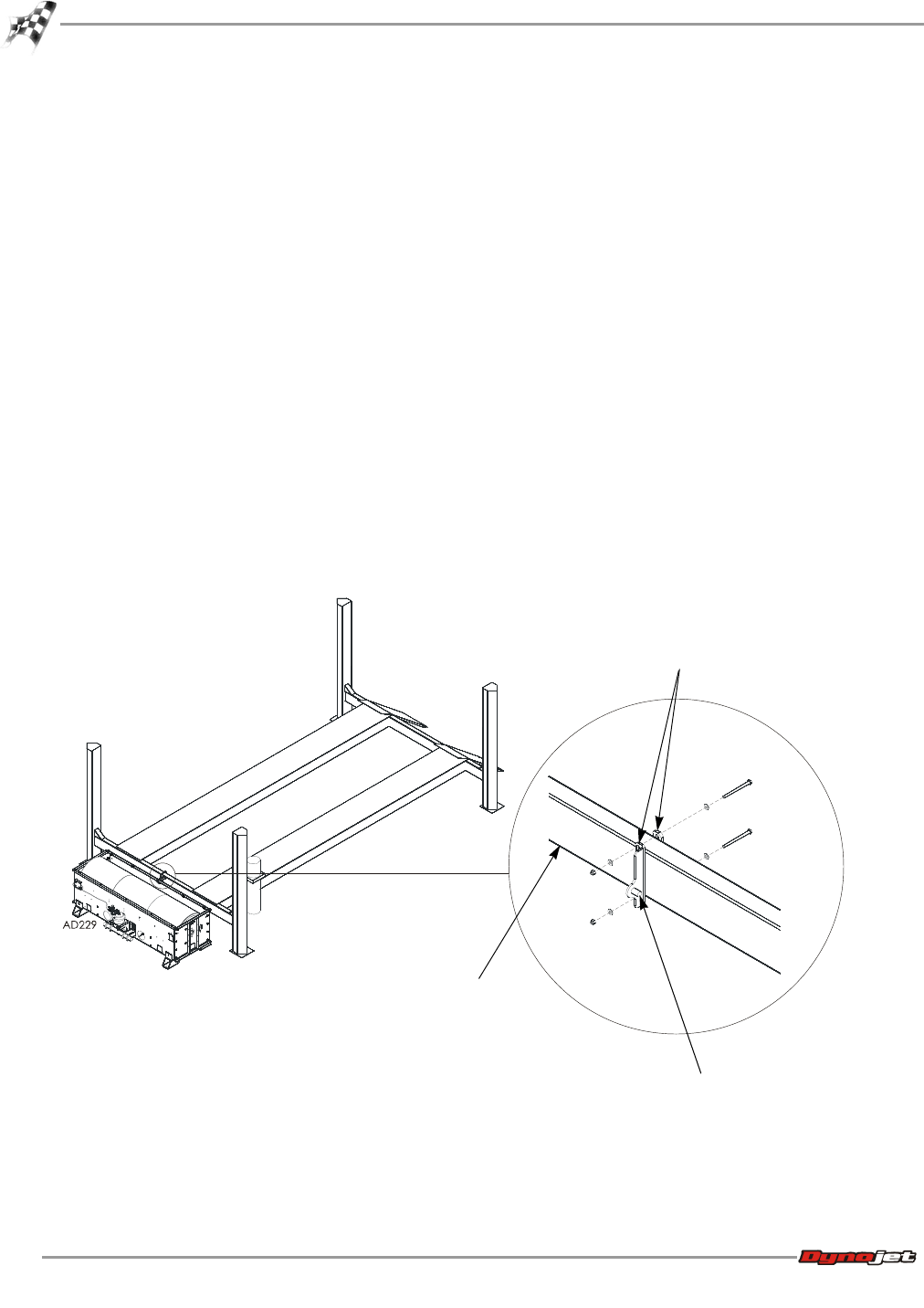
Figure 2-4: Interface Guide and Lift Cross Member
lift cross
member
interface guide
interface guide with the pin facing
the dyno and near the bottom of
the lift cross member