
Installation Guide Owner's manual
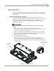
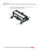
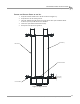
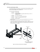
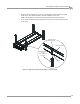
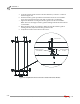
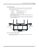

Table Of Contents
- Cover
- Copyright
- Table of Contents
- Warnings
- 1 - Specifications and Operating Requirements
- 2 - Stationary Dyno Installation
- 3 - 4WD Dyno Installation
- Unpacking and Inspecting the Dyno
- Track Assembly
- Dyno Installation
- Cable Routing
- Identifying the Cables
- Routing the Cables—Without the Eddy Current Brakes
- Wiring the Breakout Board—Without the Eddy Current Brakes
- Routing the Cables—With One Eddy Current Brake
- Wiring the Breakout Board—With One Eddy Current Brake
- Routing the Cables—With Two Eddy Current Brakes
- Wiring the Advanced Breakout Board—With Two Eddy Current Brakes
- Hydraulic Movement Installation
- Air Can Sleeve
- 4WD Dyno Movement Test
- Bridge Installation—Stationary Dyno
- Bridge Installation—4WD Dyno
- Deck Installation
- Logo Panel Installation
- 4 - Eddy Current Brake Installation
- Eddy Current Brake Installation
- Before Installing the Eddy Current Brake: Verify Optimal Brake Cooling
- Before Installing the Eddy Current Brake: Verify Mounting Holes
- Unpacking the Eddy Current Brake
- Installing the Temperature Sensor
- Installing the Bearing, Splined Shaft, and Driveline Assembly
- Installing the Eddy Current Brake
- Installing the Load Cell
- Installing the Front and Rear Brake Covers and Theta Controller
- Torque Module Installation
- Load Cell Calibration
- Eddy Current Brake Installation
- 5 - Side Deck Assembly Installation
- 6 - Basic Dyno Operation
- A - Red Head Anchor Installation
- B - Power Requirements and Installation
- C - Stationary Dyno Upgrade
- D - Bridge Extension Assembly
- E - Interface Roller Assembly Installation
- F - Torque Values
- Index
STATIONARY DYNO INSTALLATION
Dyno Installation
Version 8 Above Ground Model 424x/424xLC
2
Automotive Dynamometer Installation Guide
2-13
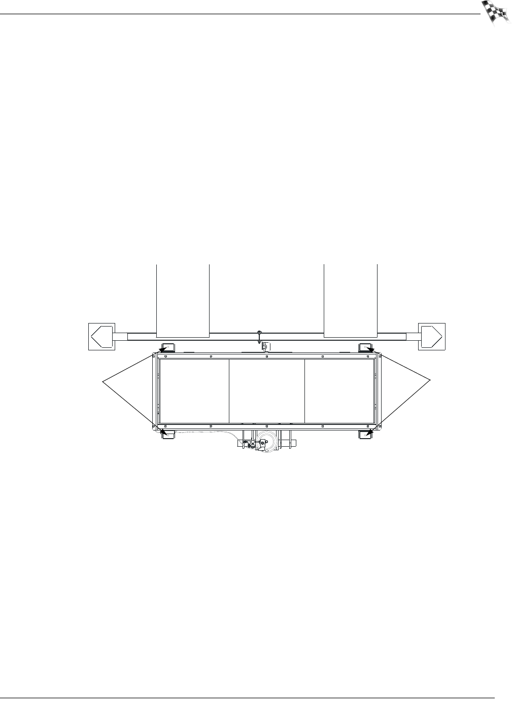
ANCHORING THE DYNO
Dynojet recommends you secure your dyno to the floor in your dyno room using
concrete anchors. Use the following instructions to secure the dyno to the floor.
You will need the following parts:
• 36923100 Washer, 3/8", Hardened, Flat, Steel (4)
• 37513200 Anchor, Redhead, 3/8" (4)
• 37518200 Redhead Anchor Installation Tool
• DM150-019-012 Bolt, 3/8-16 x 1", Hex (4)
1 Using the mounting feet as a template, mark and drill each hole needed to secure
the four dyno feet to the floor.
2 Install four Red Head anchors. Refer to Appendix A for installation instructions.
3 Secure each mounting foot to the floor using one 3/8-16 x 1-inch hex-head bolt
and one 3/8-inch flat washer.
Figure 2-7: Secure the Dyno to the Floor
INSTALLING THE EDDY CURRENT BRAKE
Refer to Chapter 4 for eddy current brake installation instructions and install your
eddy current brake at this time.
AD232
secure dyno
to floor
secure dyno
to floor
lift