
Installation Guide Owner's manual
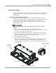
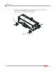
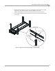
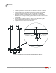
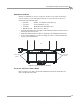

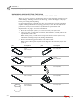
Table Of Contents
- Cover
- Copyright
- Table of Contents
- Warnings
- 1 - Specifications and Operating Requirements
- 2 - Stationary Dyno Installation
- 3 - 4WD Dyno Installation
- Unpacking and Inspecting the Dyno
- Track Assembly
- Dyno Installation
- Cable Routing
- Identifying the Cables
- Routing the Cables—Without the Eddy Current Brakes
- Wiring the Breakout Board—Without the Eddy Current Brakes
- Routing the Cables—With One Eddy Current Brake
- Wiring the Breakout Board—With One Eddy Current Brake
- Routing the Cables—With Two Eddy Current Brakes
- Wiring the Advanced Breakout Board—With Two Eddy Current Brakes
- Hydraulic Movement Installation
- Air Can Sleeve
- 4WD Dyno Movement Test
- Bridge Installation—Stationary Dyno
- Bridge Installation—4WD Dyno
- Deck Installation
- Logo Panel Installation
- 4 - Eddy Current Brake Installation
- Eddy Current Brake Installation
- Before Installing the Eddy Current Brake: Verify Optimal Brake Cooling
- Before Installing the Eddy Current Brake: Verify Mounting Holes
- Unpacking the Eddy Current Brake
- Installing the Temperature Sensor
- Installing the Bearing, Splined Shaft, and Driveline Assembly
- Installing the Eddy Current Brake
- Installing the Load Cell
- Installing the Front and Rear Brake Covers and Theta Controller
- Torque Module Installation
- Load Cell Calibration
- Eddy Current Brake Installation
- 5 - Side Deck Assembly Installation
- 6 - Basic Dyno Operation
- A - Red Head Anchor Installation
- B - Power Requirements and Installation
- C - Stationary Dyno Upgrade
- D - Bridge Extension Assembly
- E - Interface Roller Assembly Installation
- F - Torque Values
- Index
Above Ground Model 424x/424xLC
2
Automotive Dynamometer Installation Guide
CHAPTER 3
Unpacking and Inspecting the Dyno
3-2
. . . . . . . . . . . . . . . . . . . . . . . . . . . . . . . . . . .
UNPACKING AND INSPECTING THE DYNO
When you receive your dyno, examine the exterior of the shipping container for any
visible damage. If damage is detected at this stage, contact the shipper or Dynojet
before proceeding with unpacking.
Use the following steps to unload your dyno. You will need to provide equipment
capable of lifting a minimum of 2,495 kg (5,500 lb.) to move the crated dyno into
position in your dyno room. Refer to “Dynamometer Specifications and
Requirements” on page 1-4 for more information.
1 Move the crated dyno (crate 2) to a clear area near your dyno room.
2 Using a pry bar, or a large flat screwdriver, and a hammer, carefully remove the
top and sides of the crate.
Note: At this point, you will want to inspect the exterior of the dyno for any
indications of damage. Report any damage immediately.
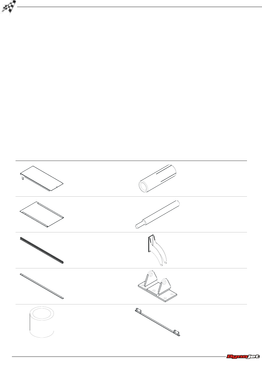
3 Remove the following parts from the crate and set aside.
Note: Some of these parts may have been shipped in the stationary dyno crate
(crate 1).
part description part description
bridge cover, stationary
dyno
P/N 21219511
anchor, redhead, 3/8" (12)
P/N 37513200
bridge cover, 4WD dyno
P/N 21219512
installation tool, redhead
anchor
P/N 37518200
rail (2)
P/N 21514282
cylinder mount, dyno
P/N 61300016
rail tie (3)
P/N 21716400
cylinder mount, floor
P/N 61300061
spacer, 424 hydraulic
movement (2)
P/N 26100000
rail tie assembly (2)
P/N 61314300