
Installation Guide Owner's manual
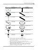
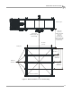
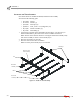
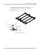
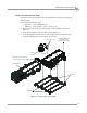
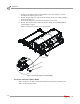
Table Of Contents
- Cover
- Copyright
- Table of Contents
- Warnings
- 1 - Specifications and Operating Requirements
- 2 - Stationary Dyno Installation
- 3 - 4WD Dyno Installation
- Unpacking and Inspecting the Dyno
- Track Assembly
- Dyno Installation
- Cable Routing
- Identifying the Cables
- Routing the Cables—Without the Eddy Current Brakes
- Wiring the Breakout Board—Without the Eddy Current Brakes
- Routing the Cables—With One Eddy Current Brake
- Wiring the Breakout Board—With One Eddy Current Brake
- Routing the Cables—With Two Eddy Current Brakes
- Wiring the Advanced Breakout Board—With Two Eddy Current Brakes
- Hydraulic Movement Installation
- Air Can Sleeve
- 4WD Dyno Movement Test
- Bridge Installation—Stationary Dyno
- Bridge Installation—4WD Dyno
- Deck Installation
- Logo Panel Installation
- 4 - Eddy Current Brake Installation
- Eddy Current Brake Installation
- Before Installing the Eddy Current Brake: Verify Optimal Brake Cooling
- Before Installing the Eddy Current Brake: Verify Mounting Holes
- Unpacking the Eddy Current Brake
- Installing the Temperature Sensor
- Installing the Bearing, Splined Shaft, and Driveline Assembly
- Installing the Eddy Current Brake
- Installing the Load Cell
- Installing the Front and Rear Brake Covers and Theta Controller
- Torque Module Installation
- Load Cell Calibration
- Eddy Current Brake Installation
- 5 - Side Deck Assembly Installation
- 6 - Basic Dyno Operation
- A - Red Head Anchor Installation
- B - Power Requirements and Installation
- C - Stationary Dyno Upgrade
- D - Bridge Extension Assembly
- E - Interface Roller Assembly Installation
- F - Torque Values
- Index
Above Ground Model 424x/424xLC
2
Automotive Dynamometer Installation Guide
CHAPTER 3
Track Assembly
3-4
. . . . . . . . . . . . . . . . . . . . . . . . . . . . . . . . . . .
TRACK ASSEMBLY
The stationary dyno must be installed before proceeding with the 4WD dyno
installation. Refer to chapter 2 for stationary dyno installation instructions.
Before installing the track assembly, layout the entire track assembly using the
following instructions and Figure 3-1 for position and alignment.
You will need the following parts:
• 37513200 Anchor, Redhead, 3/8" (10)
• 37518200 Redhead Anchor Installation Tool
1 Line up the center line of the track assembly with the center line of the stationary
dyno.
2 Measure the following distances and set the track assembly as listed below and
shown in Figure 3-1.
• The track assembly should be 128.27 cm (50.50 in.) from the stationary dyno
without the extension kit and 153.67 cm (60.50 in.) with the extension kit.
• The distance between the inside of the rails should be 184.15 cm
(72.50-inches +/- 0.06 in.).
• The distance from the first rail tie assembly to the first rail tie is 49.37 cm
(19.438 in.).
• The distance from the first rail tie assembly to the second rail tie is 103.82 cm
(40.875 in.).
• The distance from the first rail tie assembly to the third rail tie is 158.28 cm
(62.313 in.).
3 Verify the track assembly is square. Measure from corner to corner and verify
these measurements are equal.
4 Mark and drill all ten holes, five on each side of the track assembly.
5 Set the track assembly aside.
6 Install the ten Red Head anchors. Refer to Appendix A for installation instructions.