
Installation Guide Owner's manual
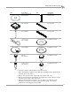
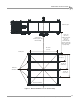
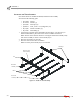
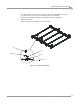
Table Of Contents
- Cover
- Copyright
- Table of Contents
- Warnings
- 1 - Specifications and Operating Requirements
- 2 - Stationary Dyno Installation
- 3 - 4WD Dyno Installation
- Unpacking and Inspecting the Dyno
- Track Assembly
- Dyno Installation
- Cable Routing
- Identifying the Cables
- Routing the Cables—Without the Eddy Current Brakes
- Wiring the Breakout Board—Without the Eddy Current Brakes
- Routing the Cables—With One Eddy Current Brake
- Wiring the Breakout Board—With One Eddy Current Brake
- Routing the Cables—With Two Eddy Current Brakes
- Wiring the Advanced Breakout Board—With Two Eddy Current Brakes
- Hydraulic Movement Installation
- Air Can Sleeve
- 4WD Dyno Movement Test
- Bridge Installation—Stationary Dyno
- Bridge Installation—4WD Dyno
- Deck Installation
- Logo Panel Installation
- 4 - Eddy Current Brake Installation
- Eddy Current Brake Installation
- Before Installing the Eddy Current Brake: Verify Optimal Brake Cooling
- Before Installing the Eddy Current Brake: Verify Mounting Holes
- Unpacking the Eddy Current Brake
- Installing the Temperature Sensor
- Installing the Bearing, Splined Shaft, and Driveline Assembly
- Installing the Eddy Current Brake
- Installing the Load Cell
- Installing the Front and Rear Brake Covers and Theta Controller
- Torque Module Installation
- Load Cell Calibration
- Eddy Current Brake Installation
- 5 - Side Deck Assembly Installation
- 6 - Basic Dyno Operation
- A - Red Head Anchor Installation
- B - Power Requirements and Installation
- C - Stationary Dyno Upgrade
- D - Bridge Extension Assembly
- E - Interface Roller Assembly Installation
- F - Torque Values
- Index
Above Ground Model 424x/424xLC
2
Automotive Dynamometer Installation Guide
CHAPTER 3
Track Assembly
3-6
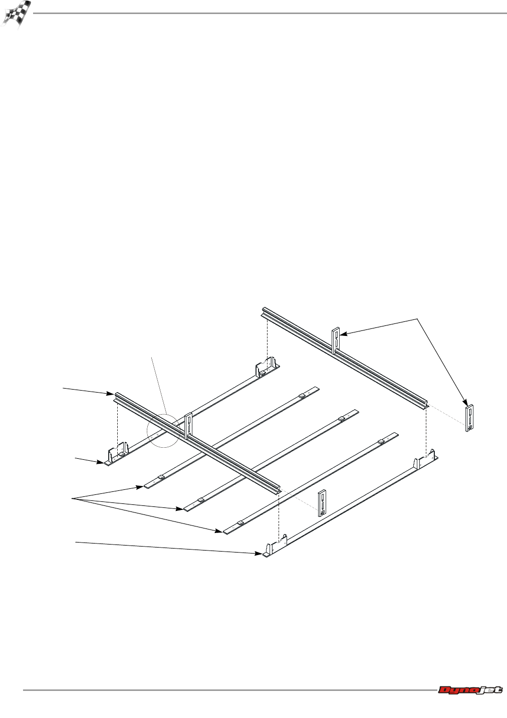
INSTALLING THE TRACK ASSEMBLY
Once all the holes are marked and drilled, install the track assembly.
You will need the following parts:
• 21514282 Rail (2)
• 21716400 Rail Tie (3)
• 31619500 Rail Clip (10)
• 36582471 Bolt, 3/8-16 x 1.5", Flange-Hex (10)
• 61314300 Rail Tie Assembly (2)
• 61314700 Rail Clamp (4)
1 Layout the first and last rail tie assemblies and the rail ties. Use the holes you
marked and drilled for placement of the rail tie assemblies and rail ties.
Note: The first rail tie has four holes for securing the cable track assembly. Verify
this rail tie assembly is closest to the stationary dyno.
2 Place the rail clamps over the rails.
3 Place the rails into the rail tie assemblies.
Note: For clarity, the stationary dyno is not shown.
Figure 3-2: Install the Track Assembly
AD045
rail clamps
rail
first rail tie
assembly
last rail tie
assembly
rail tie
holes for cable
track assembly