
Installation Guide Owner's manual
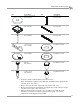
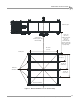
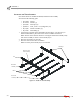
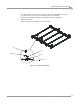
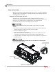
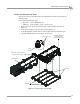
Table Of Contents
- Cover
- Copyright
- Table of Contents
- Warnings
- 1 - Specifications and Operating Requirements
- 2 - Stationary Dyno Installation
- 3 - 4WD Dyno Installation
- Unpacking and Inspecting the Dyno
- Track Assembly
- Dyno Installation
- Cable Routing
- Identifying the Cables
- Routing the Cables—Without the Eddy Current Brakes
- Wiring the Breakout Board—Without the Eddy Current Brakes
- Routing the Cables—With One Eddy Current Brake
- Wiring the Breakout Board—With One Eddy Current Brake
- Routing the Cables—With Two Eddy Current Brakes
- Wiring the Advanced Breakout Board—With Two Eddy Current Brakes
- Hydraulic Movement Installation
- Air Can Sleeve
- 4WD Dyno Movement Test
- Bridge Installation—Stationary Dyno
- Bridge Installation—4WD Dyno
- Deck Installation
- Logo Panel Installation
- 4 - Eddy Current Brake Installation
- Eddy Current Brake Installation
- Before Installing the Eddy Current Brake: Verify Optimal Brake Cooling
- Before Installing the Eddy Current Brake: Verify Mounting Holes
- Unpacking the Eddy Current Brake
- Installing the Temperature Sensor
- Installing the Bearing, Splined Shaft, and Driveline Assembly
- Installing the Eddy Current Brake
- Installing the Load Cell
- Installing the Front and Rear Brake Covers and Theta Controller
- Torque Module Installation
- Load Cell Calibration
- Eddy Current Brake Installation
- 5 - Side Deck Assembly Installation
- 6 - Basic Dyno Operation
- A - Red Head Anchor Installation
- B - Power Requirements and Installation
- C - Stationary Dyno Upgrade
- D - Bridge Extension Assembly
- E - Interface Roller Assembly Installation
- F - Torque Values
- Index
Above Ground Model 424x/424xLC
2
Automotive Dynamometer Installation Guide
CHAPTER 3
Dyno Installation
3-8
. . . . . . . . . . . . . . . . . . . . . . . . . . . . . . . . . . .
DYNO INSTALLATION
With the track assembly installed and secured to the floor, you are ready to install the
4WD dyno. This section will walk you through removing the dyno from the crate and
securing the dyno to the track.
REMOVING THE DYNO FROM THE CRATE
You will need to provide equipment capable of lifting a minimum of 2,495 kg
(5,500 lb.) to lift the dyno off the crate and into position in your dyno room. You will
also need a pair of straps capable of supporting the same weight. Dynojet
recommends using two 2-inch x 6-foot single loop style straps.
#
RECORD
Be sure you record the dynamometer number on the inside cover of this
manual
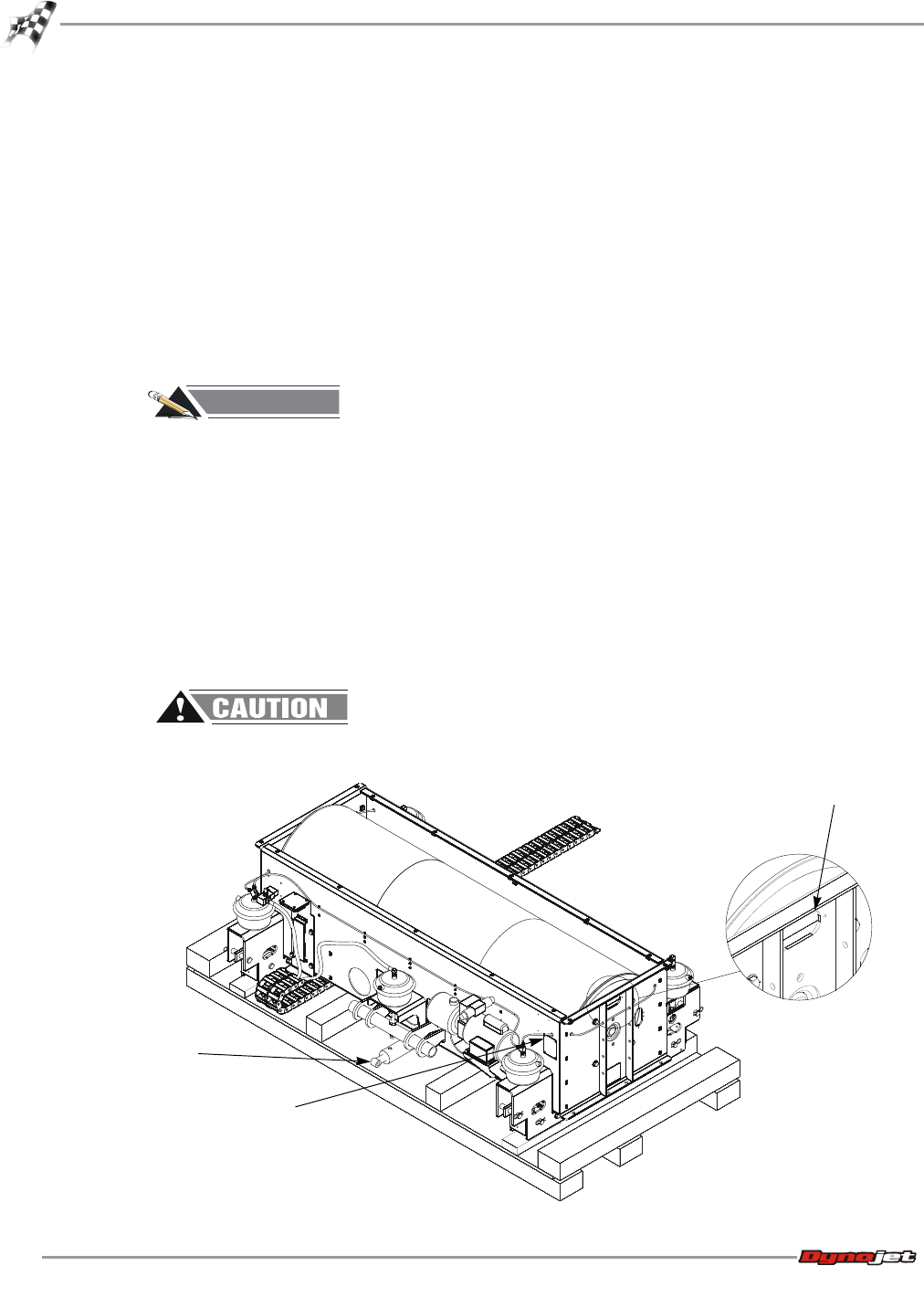
1 Route the loop strap through the opening in the dyno frame and through itself.
Pull the strap tight. Do this on each side of the dyno frame.
2 Push the forklift forks together.
3 Place each loop strap over both forks.
Note: The straps must be the same length and meet in the middle. Verify each
loop strap is over both forks to prevent the forks from being pulled apart.
4 Using the forklift, carefully lift the dyno off the crate and move it into position in
your dyno room.
Use caution when handling the hydraulic ram and the hoses connecting the
ram to the hydraulic motor.
Figure 3-4: Loop Strap Placement
AD351
dyno number
place strap through
opening in dyno frame
hydraulic ram