
Installation Guide Owner's manual
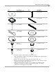
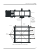
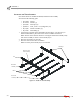
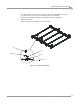
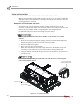
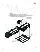
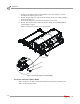
Table Of Contents
- Cover
- Copyright
- Table of Contents
- Warnings
- 1 - Specifications and Operating Requirements
- 2 - Stationary Dyno Installation
- 3 - 4WD Dyno Installation
- Unpacking and Inspecting the Dyno
- Track Assembly
- Dyno Installation
- Cable Routing
- Identifying the Cables
- Routing the Cables—Without the Eddy Current Brakes
- Wiring the Breakout Board—Without the Eddy Current Brakes
- Routing the Cables—With One Eddy Current Brake
- Wiring the Breakout Board—With One Eddy Current Brake
- Routing the Cables—With Two Eddy Current Brakes
- Wiring the Advanced Breakout Board—With Two Eddy Current Brakes
- Hydraulic Movement Installation
- Air Can Sleeve
- 4WD Dyno Movement Test
- Bridge Installation—Stationary Dyno
- Bridge Installation—4WD Dyno
- Deck Installation
- Logo Panel Installation
- 4 - Eddy Current Brake Installation
- Eddy Current Brake Installation
- Before Installing the Eddy Current Brake: Verify Optimal Brake Cooling
- Before Installing the Eddy Current Brake: Verify Mounting Holes
- Unpacking the Eddy Current Brake
- Installing the Temperature Sensor
- Installing the Bearing, Splined Shaft, and Driveline Assembly
- Installing the Eddy Current Brake
- Installing the Load Cell
- Installing the Front and Rear Brake Covers and Theta Controller
- Torque Module Installation
- Load Cell Calibration
- Eddy Current Brake Installation
- 5 - Side Deck Assembly Installation
- 6 - Basic Dyno Operation
- A - Red Head Anchor Installation
- B - Power Requirements and Installation
- C - Stationary Dyno Upgrade
- D - Bridge Extension Assembly
- E - Interface Roller Assembly Installation
- F - Torque Values
- Index
Above Ground Model 424x/424xLC
2
Automotive Dynamometer Installation Guide
CHAPTER 3
Dyno Installation
3-10
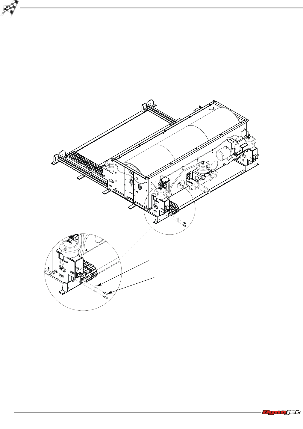
5 Secure the rail clamps to the cradle assembly on the dyno using two 3/8-inch
shoulder bolts and two spacers each.
6 Replace the pins and cotter pins removed earlier from the four cradle assemblies
as shown in Figure 3-5.
7 Move the rail clamps up and down and verify they move freely.
8 Roll the dyno back and forth and verify the rail clamps are not binding and the
track assembly is square.
Note: For clarity, the stationary dyno is not shown.
Figure 3-6: Secure the Dyno to the Rail Clamps
INSTALLING THE EDDY CURRENT BRAKE
Refer to Chapter 4 for eddy current brake installation instructions and install your
eddy current brake at this time.
AD353
spacer
bolt