
Installation Guide Owner's manual
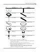
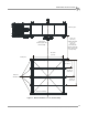
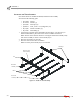
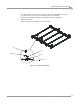
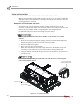
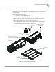
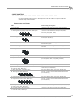
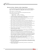
Table Of Contents
- Cover
- Copyright
- Table of Contents
- Warnings
- 1 - Specifications and Operating Requirements
- 2 - Stationary Dyno Installation
- 3 - 4WD Dyno Installation
- Unpacking and Inspecting the Dyno
- Track Assembly
- Dyno Installation
- Cable Routing
- Identifying the Cables
- Routing the Cables—Without the Eddy Current Brakes
- Wiring the Breakout Board—Without the Eddy Current Brakes
- Routing the Cables—With One Eddy Current Brake
- Wiring the Breakout Board—With One Eddy Current Brake
- Routing the Cables—With Two Eddy Current Brakes
- Wiring the Advanced Breakout Board—With Two Eddy Current Brakes
- Hydraulic Movement Installation
- Air Can Sleeve
- 4WD Dyno Movement Test
- Bridge Installation—Stationary Dyno
- Bridge Installation—4WD Dyno
- Deck Installation
- Logo Panel Installation
- 4 - Eddy Current Brake Installation
- Eddy Current Brake Installation
- Before Installing the Eddy Current Brake: Verify Optimal Brake Cooling
- Before Installing the Eddy Current Brake: Verify Mounting Holes
- Unpacking the Eddy Current Brake
- Installing the Temperature Sensor
- Installing the Bearing, Splined Shaft, and Driveline Assembly
- Installing the Eddy Current Brake
- Installing the Load Cell
- Installing the Front and Rear Brake Covers and Theta Controller
- Torque Module Installation
- Load Cell Calibration
- Eddy Current Brake Installation
- 5 - Side Deck Assembly Installation
- 6 - Basic Dyno Operation
- A - Red Head Anchor Installation
- B - Power Requirements and Installation
- C - Stationary Dyno Upgrade
- D - Bridge Extension Assembly
- E - Interface Roller Assembly Installation
- F - Torque Values
- Index
4WD DYNO INSTALLATION
Cable Routing
Version 8 Above Ground Model 424x/424xLC
2
Automotive Dynamometer Installation Guide
3-11
. . . . . . . . . . . . . . . . . . . . . . . . . . . . . . . . . . .
CABLE ROUTING
Use the following instructions to identify and route the cables for dynos with and
without eddy current brakes.
IDENTIFYING THE CABLES
cable brief routing description
A - 25-pin cable connects to the dyno electronics (P/N 42924250)
B - data acquisition (pickup card) cable, stationary dyno
C - data acquisition (pickup card) cable, 4WD dyno
four wires (red, white, black, shield) and ferrules,
connects to the Breakout board (P/N 66954001,
stationary; 66953001, 4WD)
D - brake signal cable two wires and ferrules, connects to the Breakout
board (P/N 76950213)
E - air hose, short (16 feet) connects to the barbed fitting on the air brake can on
the stationary dyno
F - air hose, long (18 feet) connects to the T fitting on the stationary dyno brake
solenoid
G - 4WD power cable connects to the power supply (P/N 76952008)
H - hydraulic pump power cable connects to your 110VAC or 220VAC power outlet
I - dyno movement pendant cable connects to the dyno movement pendant
(P/N 76953005, cable; 76953004, pendant)
The following cables are used with the eddy current brake(s):
J - load cell cable, stationary dyno
K - load cell cable, 4WD dyno
connects to the torque module on the dyno
electronics (P/N 76950505)
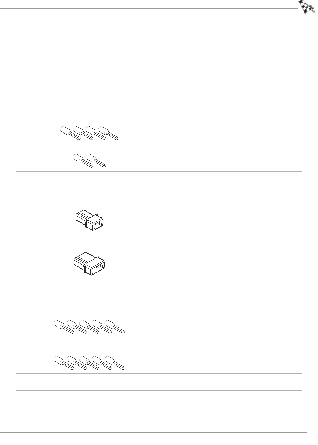
L - theta signal cable, stationary dyno
M - theta signal cable, 4WD dyno
five wires (black, white, red, green, shield) and
ferrules, connects to the Advanced Breakout board
(P/N 76950413)
N - temperature sensor cable, stationary dyno
O - temperature sensor cable, 4WD dyno
five wires (black, white, red, green, shield) and
ferrules, connects to the Advanced Breakout board
(P/N 76950420)
P - theta power cable, stationary dyno
Q - theta power cable, 4WD dyno
connects to your 240V power source (P/N 76950311)
R - controller cable, stationary dyno
S - controller cable, 4WD dyno
connects to the theta controller (P/N 66952003)