
Installation Guide Owner's manual
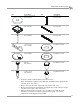
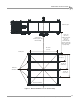
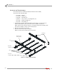
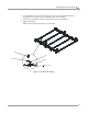
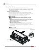
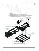
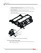
Table Of Contents
- Cover
- Copyright
- Table of Contents
- Warnings
- 1 - Specifications and Operating Requirements
- 2 - Stationary Dyno Installation
- 3 - 4WD Dyno Installation
- Unpacking and Inspecting the Dyno
- Track Assembly
- Dyno Installation
- Cable Routing
- Identifying the Cables
- Routing the Cables—Without the Eddy Current Brakes
- Wiring the Breakout Board—Without the Eddy Current Brakes
- Routing the Cables—With One Eddy Current Brake
- Wiring the Breakout Board—With One Eddy Current Brake
- Routing the Cables—With Two Eddy Current Brakes
- Wiring the Advanced Breakout Board—With Two Eddy Current Brakes
- Hydraulic Movement Installation
- Air Can Sleeve
- 4WD Dyno Movement Test
- Bridge Installation—Stationary Dyno
- Bridge Installation—4WD Dyno
- Deck Installation
- Logo Panel Installation
- 4 - Eddy Current Brake Installation
- Eddy Current Brake Installation
- Before Installing the Eddy Current Brake: Verify Optimal Brake Cooling
- Before Installing the Eddy Current Brake: Verify Mounting Holes
- Unpacking the Eddy Current Brake
- Installing the Temperature Sensor
- Installing the Bearing, Splined Shaft, and Driveline Assembly
- Installing the Eddy Current Brake
- Installing the Load Cell
- Installing the Front and Rear Brake Covers and Theta Controller
- Torque Module Installation
- Load Cell Calibration
- Eddy Current Brake Installation
- 5 - Side Deck Assembly Installation
- 6 - Basic Dyno Operation
- A - Red Head Anchor Installation
- B - Power Requirements and Installation
- C - Stationary Dyno Upgrade
- D - Bridge Extension Assembly
- E - Interface Roller Assembly Installation
- F - Torque Values
- Index

Above Ground Model 424x/424xLC
2
Automotive Dynamometer Installation Guide
CHAPTER 3
Cable Routing
3-12
ROUTING THE CABLES—WITHOUT THE EDDY CURRENT BRAKES
Use these instructions for routing cables without the eddy current brake. Refer to
page 3-15 for more information on routing cables with one eddy current brake and
page 3-19 for more information on routing cables with two eddy current brakes.
Refer to Figure 3-7 for cable locations.
Refer to page 3-14 for more information on wiring the Breakout board.
You will need the following parts:
• DM150-009-003 Washer, 1/4", Flat (4)
• DM150-011-005 Bolt, 1/4" x 1/2", Hex (4)
1 Secure the first and second cable tracks to the front rail tie assembly using two
1/4-20 x 1/2-inch hex-head screws and two washers each.
2 Route the 25-pin cable (A) from the Breakout board to the dyno electronics.
Connect the 25-pin cable to the dyno electronics.
Refer to Figure 1-6 for information on where to connect the 25-pin cable.
3 Route the pickup card cable (B) from the stationary dyno to the Breakout board.
Refer to page 3-14 for more information on wiring the Breakout board.
4 Route the pickup card cable (C) from the first cable track to the Breakout board.
Refer to page 3-14 for more information on wiring the Breakout board.
5 Route the brake signal cable (D) from the first cable track to the Breakout board.
Refer to page 3-14 for more information on wiring the Breakout board.
6 Route the air hose (E) from the second cable track to the T fitting on the
stationary dyno brake solenoid.
7 Route the long air hose (F) from the second cable track to the barbed fitting on
the air brake can on the stationary dyno.
Note: Verify the stationary dyno has clean dry air regulated between 100-140 psi
supplied to the remaining barbed fitting on the brake solenoid assembly.
The air brake comes installed with a hose barb for a 3/8-inch inside diameter air
hose. If your hose does not have an inside diameter of 3/8-inch then you will need
an air hose nipple (1/4-inch NPT) to connect your clean, dry shop air supply to
the dyno. Once the pressure is connected, the air brake is ready to use.
8 Route the power cable (G) from the first cable track and connect to the power
supply. Plug the power supply into your power source.
9 Connect the power supply to the dyno electronics. Plug the power supply into
your power source.
10 Route the hydraulic pump power cable (H) from the first cable track and connect
to a 110VAC or 220VAC outlet. Refer to page 3-28 for more information on wiring
the hydraulic pump motor.
11 Route the dyno movement pendant cable (I) from the first cable track and
connect to the pendant.