
Installation Guide Owner's manual
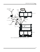
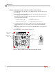
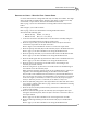
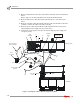
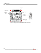
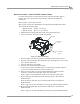
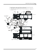
Table Of Contents
- Cover
- Copyright
- Table of Contents
- Warnings
- 1 - Specifications and Operating Requirements
- 2 - Stationary Dyno Installation
- 3 - 4WD Dyno Installation
- Unpacking and Inspecting the Dyno
- Track Assembly
- Dyno Installation
- Cable Routing
- Identifying the Cables
- Routing the Cables—Without the Eddy Current Brakes
- Wiring the Breakout Board—Without the Eddy Current Brakes
- Routing the Cables—With One Eddy Current Brake
- Wiring the Breakout Board—With One Eddy Current Brake
- Routing the Cables—With Two Eddy Current Brakes
- Wiring the Advanced Breakout Board—With Two Eddy Current Brakes
- Hydraulic Movement Installation
- Air Can Sleeve
- 4WD Dyno Movement Test
- Bridge Installation—Stationary Dyno
- Bridge Installation—4WD Dyno
- Deck Installation
- Logo Panel Installation
- 4 - Eddy Current Brake Installation
- Eddy Current Brake Installation
- Before Installing the Eddy Current Brake: Verify Optimal Brake Cooling
- Before Installing the Eddy Current Brake: Verify Mounting Holes
- Unpacking the Eddy Current Brake
- Installing the Temperature Sensor
- Installing the Bearing, Splined Shaft, and Driveline Assembly
- Installing the Eddy Current Brake
- Installing the Load Cell
- Installing the Front and Rear Brake Covers and Theta Controller
- Torque Module Installation
- Load Cell Calibration
- Eddy Current Brake Installation
- 5 - Side Deck Assembly Installation
- 6 - Basic Dyno Operation
- A - Red Head Anchor Installation
- B - Power Requirements and Installation
- C - Stationary Dyno Upgrade
- D - Bridge Extension Assembly
- E - Interface Roller Assembly Installation
- F - Torque Values
- Index
Above Ground Model 424x/424xLC
2
Automotive Dynamometer Installation Guide
CHAPTER 3
Cable Routing
3-14
WIRING THE BREAKOUT BOARD—WITHOUT THE EDDY CURRENT BRAKES
1 Attach the pickup card cable (B, C) to the Breakout board. This cable may already
be connected.
The pickup card cable (B) from the stationary dyno has four wires which connect
to the wiring block labeled DRUM 1.
The pickup card cable (C) from the 4WD dyno has four wires which connect to
the wiring block labeled DRUM 2.
2 Attach the brake signal cable (D) to the Breakout board. The brake signal cable
from the 4WD dyno has two wires which connect to the wiring block labeled
BRAKE.
Note: There will already be wires connected to BRAKE; add the brake signal wires
to this location.
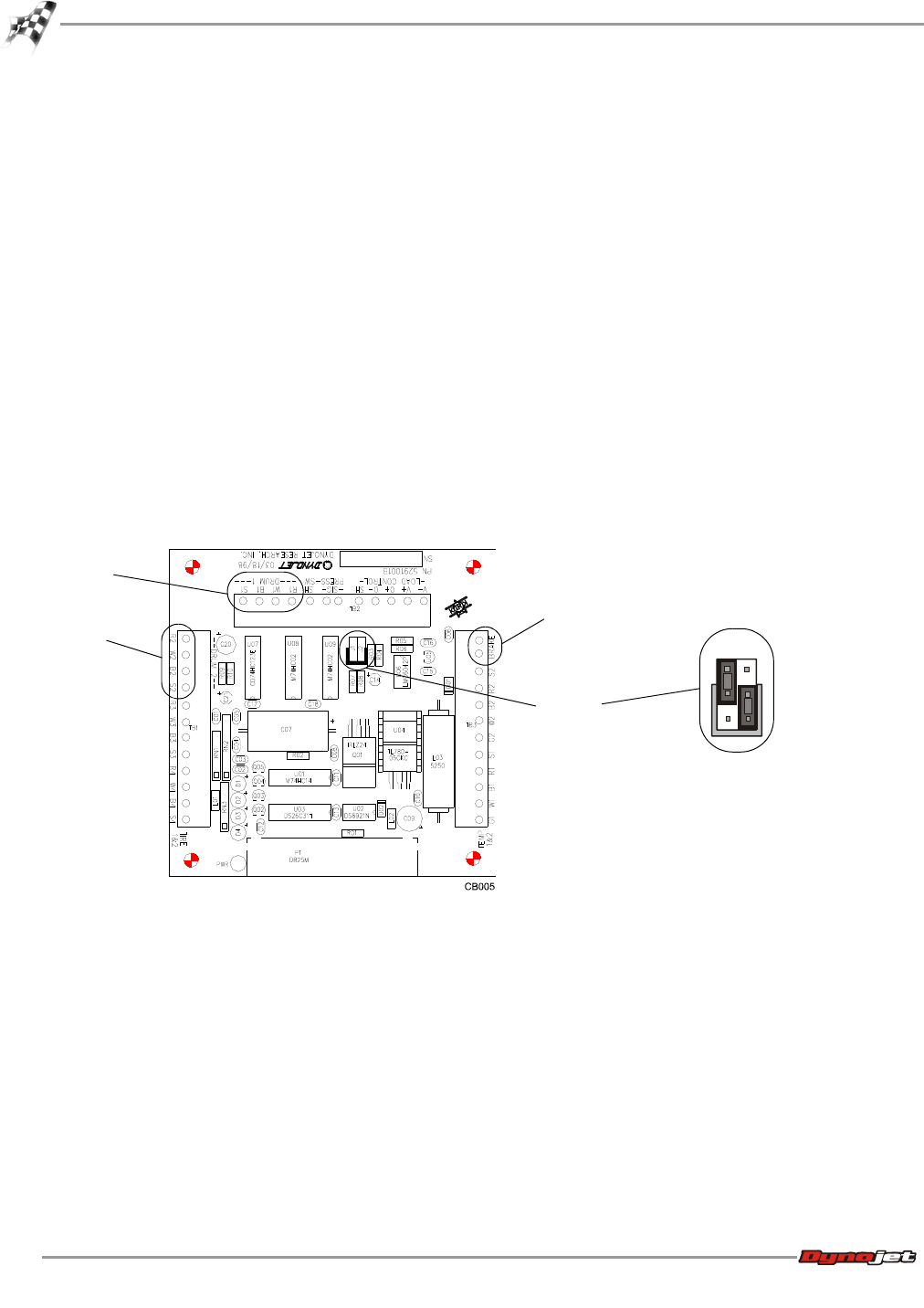
3 Verify the jumpers are set as shown in Figure 3-8.
Figure 3-8: Wiring the Breakout Board—Without the Eddy Current Brakes
• Red wire connects to R1 • Black wire connects to B1
• White wire connects to W1 • Ground (shield) wire connects to S1
jumpers
J1 and J2
four wheel drive
with no eddy
current brake
jumper settings
pickup card
stationary
pickup card
4WD
brake signal
J1
J2